Model G0920 (Mfd. Since 10/20)
-41-
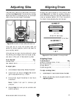
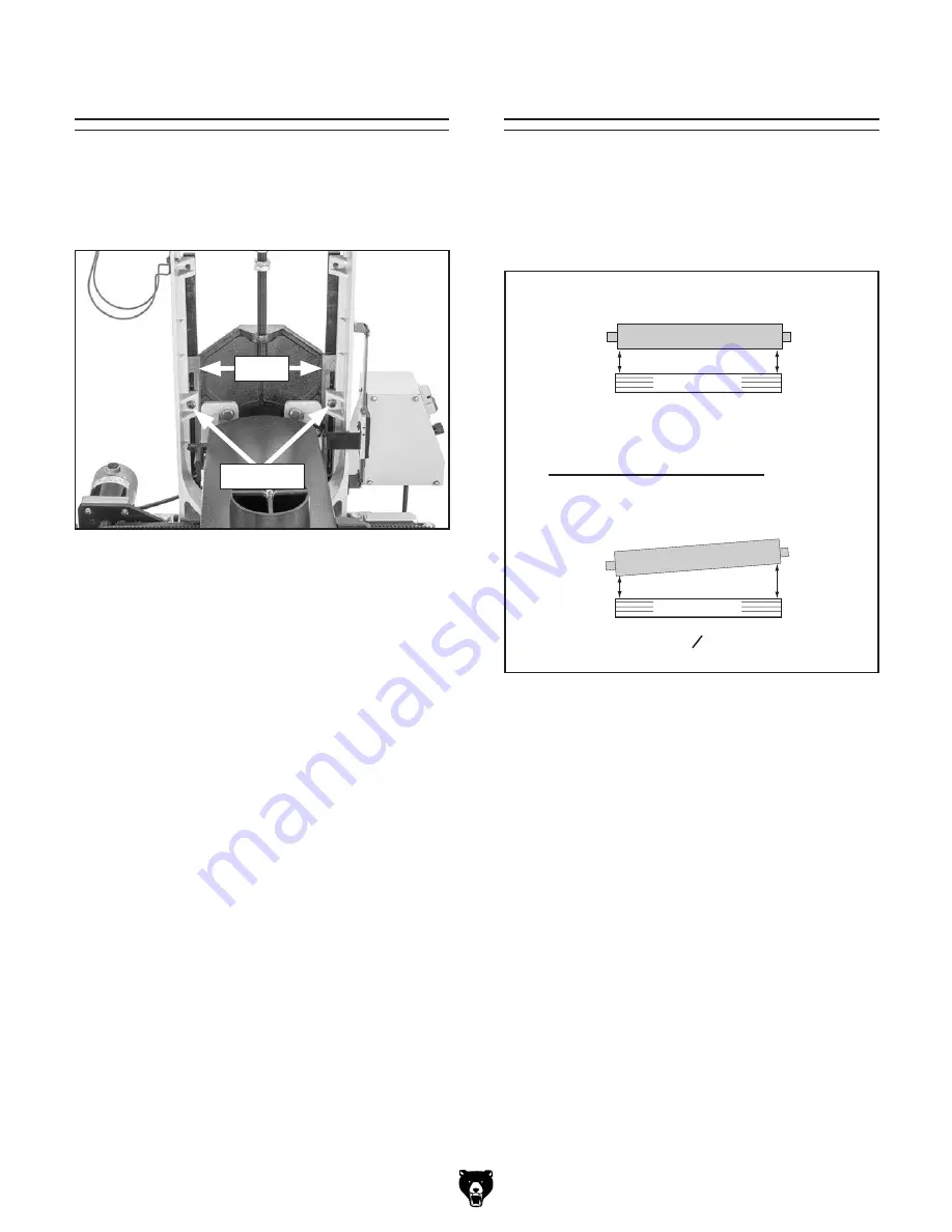
The gibs apply pressure to the slides of the sand-
ing head (see
Figure 58). This allows the sanding
head assembly to accurately move up and down
when using the drum height handwheel.
Figure 58. Location of rear slide and lock nut.
If the gibs are too loose, the sanding drum will
deflect up during operation, which will result in
poor sanding results.
If the gibs are too tight, it will be difficult to adjust
the sanding drum height, which will cause exces-
sive wear on the parts of the elevation system.
Adjusting Gibs
Tools Needed
Qty
Socket 13mm ..................................................... 1
Hex Wrench 6mm .............................................. 1
To adjust gibs:
1. DISCONNECT MACHINE FROM POWER!
2. Adjust lock nuts shown in Figure 58 on both
gibs an equal amount, by
1
/
4
turns.
3. Rotate drum height handwheel to test drum
movement.
Note: Tighten lock nuts to increase gib
pressure.
4. Repeat Step 2–3 until you are satisfied with
drum movement.
Slides
Lock Nuts
Aligning Drum
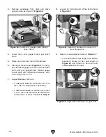
Aligning the drum parallel to the conveyor belt
(see
Figure 59) is critical for sanding accuracy.
Care should be taken to make the tolerances as
close as possible (within 0.010" from one side to
the other) when adjusting the drum height.
(Front View)
CORRECT
INCORRECT
B
A
B
A
B
=
A
=
A
B
(Within 0.010" side-to-side)
Sanding Drum
Sanding Drum
Conveyor Belt
Conveyor Belt
Figure 59. Drum parallel to conveyor belt.
Tools Needed:
Qty
Wrench or Socket 13mm, 17mm ....................... 1
Hex Wrench 6mm .............................................. 1
Gauge Blocks .................................................... 2
Feeler Gauge Set .............................................. 1
To align sanding drum:
1. DISCONNECT MACHINE FROM POWER!
2. Make sure gibs are properly adjusted (refer to
Adjusting Gibs).
Aligning Drum
Summary of Contents for G0920
Page 60: ......


