-42-
Model G0920 (Mfd. Since 10/20)
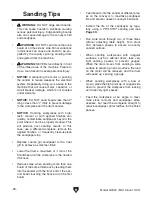
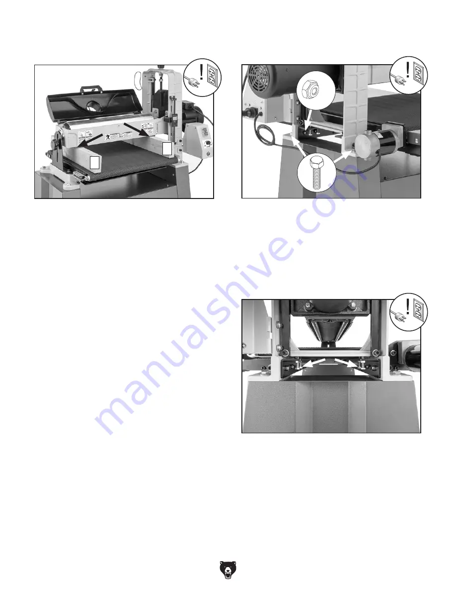
3. Remove sandpaper from drum and place
gauge blocks as shown in
Figure 60.
4. Lower drum until gauge blocks just touch
drum.
5. Raise drum one full crank of handwheel.
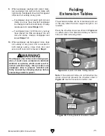
6. Starting at A board (see Figure 60), find larg-
est size feeler gauge that can pass between
drum and your gauge block. (Feeler gauge
should slide with moderate resistance, with-
out forcing drum to roll.)
7. Repeat Step 6 at B board.
— If difference between A and B is 0.010" or
less, then no adjustment is necessary.
— If difference between A and B is more than
0.010", then one end must be adjusted to
within 0.010" of other. Proceed to
Step 8.
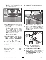
Figure 60. Example of gauge blocks placed
under drum.
A
B
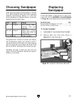
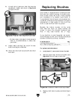
8. Loosen (4) lock nuts and (2) hex bolts shown
in
Figure 61.
9. Refer to measurements taken in Steps 6–7.
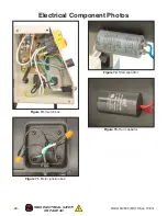
— If A measurement was larger than B mea-
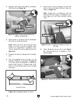
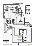
surement, loosen (2) hex nuts shown in
Figure 62 and tighten (2) hex bolts until
measurements are equal.
Figure 62. Adjustment hardware for right side.
Figure 61. Mounting hardware to loosen for
drum adjustment.
x 4
Summary of Contents for G0920
Page 60: ......

