background image

WARRANTY & RETURNS

Grizzly Industrial, Inc. warrants every product it sells for a period of 

1 year to the original purchaser from 

the date of purchase. This warranty does not apply to defects due directly or indirectly to misuse, abuse, 
negligence, accidents, repairs or alterations or lack of maintenance. This is Grizzly’s sole written warranty 
and any and all warranties that may be implied by law, including any merchantability or fitness, for any par-
ticular purpose, are hereby limited to the duration of this written warranty. We do not warrant or represent 
that the merchandise complies with the provisions of any law or acts unless the manufacturer so warrants. 
In no event shall Grizzly’s liability under this warranty exceed the purchase price paid for the product and 
any legal actions brought against Grizzly shall be tried in the State of Washington, County of Whatcom.

We shall in no event be liable for death, injuries to persons or property or for incidental, contingent, special, 
or consequential damages arising from the use of our products.

The manufacturers reserve the right to change specifications at any time because they constantly strive to 
achieve better quality equipment. We make every effort to ensure that our products meet high quality and 
durability standards and we hope you never need to use this warranty.

In the event you need to use this warranty, contact us by mail or phone and give us all the details. We will 
then issue you a “Return Number,’’ which must be clearly posted on the outside as well as the inside of 
the carton. We will not accept any item back without this number. Proof of purchase must accompany the 
merchandise. 

Please feel free to write or call us if you have any questions about the machine or the manual. 

Thank you again for your business and continued support. We hope to serve you again soon.

To take advantage of this warranty, you must register it at https://www.grizzly.com/forms/warranty, or 
you can scan the QR code below to be automatically directed to our warranty registration page. Enter all 
applicable information for the product.

WARRANTY

Summary of Contents for G0920

Page 1: ...C WARNING NO PORTION OF THIS MANUAL MAY BE REPRODUCED IN ANY SHAPE OR FORM WITHOUT THE WRITTEN APPROVAL OF GRIZZLY INDUSTRIAL INC CS21435 PRINTED IN TAIWAN V1 12 20 MODEL G0920 22 SINGLE DRUM SANDER OWNER S MANUAL For models manufactured since 10 20 ...

Page 2: ...ng grinding tool integrity and the usage of personal protective equipment The manufacturer will not be held liable for injury or property damage from negligence improper training machine modifications or misuse Some dust created by power sanding sawing grinding drilling and other construction activities contains chemicals known to the State of California to cause cancer birth defects or other repr...

Page 3: ...Using Digital Depth Gauge 26 Adjusting Conveyor Feed Rate 27 Sanding Tips 28 Choosing Sandpaper 29 Replacing Sandpaper 29 Folding Extension Tables 31 SECTION 5 ACCESSORIES 32 SECTION 6 MAINTENANCE 33 Schedule 33 Cleaning Machine 33 Cleaning Sanding Belts 33 Lubrication 34 SECTION 7 SERVICE 35 Troubleshooting 35 Tracking Tensioning Conveyor Belt 38 Replacing Conveyor Belt 39 Making Blocks 40 Adjust...

Page 4: ...ade every effort to be exact with the instruc tions specifications drawings and photographs in this manual Sometimes we make mistakes but our policy of continuous improvement also means that sometimes the machine you receive is slightly different than shown in the manual If you find this to be the case and the difference between the manual and machine leaves you confused or unsure about something ...

Page 5: ...eyor belt or distance between two depths D ON OFF Buttons Turn motor ON and OFF E Conveyor Feed Rate Dial Rotate dial clock wise to increase conveyor belt feed rate or counterclockwise to decrease feed rate Conveyor feed rate ranges from 0 20 FPM F Circuit Breaker Reset Button Trips during excessive sanding operation when workload overloads circuit Press button to reset break er G Extension Tables...

Page 6: ...ngth x Width x Height 45 x 26 x 26 in Must Ship Upright Yes Carton 2 Type Cardboard Box Content Stand Weight 105 lbs Length x Width x Height 34 x 27 x 14 in Must Ship Upright Yes Electrical Power Requirement 230V Single Phase 60 Hz Full Load Current Rating 8 5A Minimum Circuit Size 15A Connection Type Cord Plug Power Cord Included Yes Power Cord Length 60 in Power Cord Gauge 14 AWG Plug Included Y...

Page 7: ...pe Aluminum Infeed Sanding Drum Size 5 in Construction Conveyor Belt Rubber Body Steel Paint Type Finish Powder Coated Other Related Information Floor To Table Height 36 1 4 in Sanding Belt Tension Spring Loaded Number of Pressure Rollers 2 Pressure Roller Type Steel Pressure Roller Size 3 4 in Conveyor Belt Length 46 in Conveyor Belt Width 22 in Belt Roller Size 1 3 4 in Number of Dust Ports 1 Du...

Page 8: ...id proof DANGEROUS ENVIRONMENTS Do not use machinery in areas that are wet cluttered or have poor lighting Operating machinery in these areas greatly increases the risk of accidents and injury MENTAL ALERTNESS REQUIRED Full mental alertness is required for safe operation of machin ery Never operate under the influence of drugs or alcohol when tired or when distracted For Your Own Safety Read Instr...

Page 9: ... moving parts or flying debris Make sure they are properly installed undamaged and working correctly BEFORE operating machine FORCING MACHINERY Do not force machine It will do the job safer and better at the rate for which it was designed NEVER STAND ON MACHINE Serious injury may occur if machine is tipped or if the cutting tool is unintentionally contacted STABLE MACHINE Unexpected movement dur i...

Page 10: ...minimum specifications listed in Machine Data Sheet FEEDING WORKPIECE Placing fingers between workpiece and conveyor can result in pinching injuries or possibly getting trapped and pulled into sanding area of machine DO NOT place fingers under bottom of workpiece while feeding it into sander SANDING DUST Sanding creates large amounts of fine airborne dust that can lead to eye injury or serious res...

Page 11: ...or fire may result especially if connected to an undersized circuit To reduce the risk of these hazards avoid over loading the machine during operation and make sure it is connected to a power supply circuit that meets the specified circuit requirements For your own safety and protection of property consult an electrician if you are unsure about wiring practices or electrical codes in your area No...

Page 12: ...ny extension cord used with this machine must be in good condition and contain a ground wire and matching plug receptacle Additionally it must meet the following size requirements Minimum Gauge Size 12 AWG Maximum Length Shorter is Better 50 ft Figure 1 Typical 6 15 plug and receptacle Grounding Pin Current Carrying Prongs 6 15 PLUG GROUNDED 6 15 RECEPTACLE Grounding Requirements This machine MUST...

Page 13: ...y lifting machine or some of its parts To reduce this risk get help from other people and use a forklift or other lifting equipment rated for weight of this machine The following items are needed but not included for the setup assembly of this machine This machine was carefully packaged for safe transport When unpacking separate all enclosed items from packaging materials and inspect them for ship...

Page 14: ...sher we will gladly replace them or for the sake of expediency replacements can be obtained at your local hardware store Figure 2 Cabinet inventory Cabinet Figure 2 Qty A Front Panel 1 B Rear Panel 1 C Left Side Panel 1 D Right Side Panel 1 E Bottom Panel 1 F Top Panel 1 G Rubber Feet 4 H Partition Panels 2 I Slotted Screws 5 16 18 x 3 4 4 J Hex Bolts M8 1 25 x 40 4 K Hex Bolts M8 1 25 x 25 8 L Ph...

Page 15: ...2mm 1 BB Open End Wrench 12 x 14mm 1 BC Open End Wrench 14 x 17mm 1 Extension Tables Figure 3 Qty U Extension Tables 2 V Right Table Mounting Blocks 2 W Left Table Mounting Blocks 2 X Right Table Folding Brackets 2 Y Left Table Folding Brackets 2 Z Table Mounting Brackets 2 AA Shoulder Screws M10 1 5 x 65 4 AB Flat Head Screws M8 1 25 x 25 8 AC Carriage Bolts M8 1 25 x 20 8 AD Cap Screws M8 1 25 x...

Page 16: ... 14 Model G0920 Mfd Since 10 20 Hardware Recognition Chart USE THIS CHART TO MATCH UP HARDWARE DURING THE INVENTORY AND ASSEMBLY PROCESS 5mm 5mm Flat Head Cap Screw ...

Page 17: ... space allocation Physical Environment The physical environment where the machine is operated is important for safe operation and lon gevity of machine components For best results operate this machine in a dry environment that is free from excessive moisture hazardous chemi cals airborne abrasives or extreme conditions Extreme conditions for this type of machinery are generally those where the amb...

Page 18: ...re 7 Note Nubs on feet should face up to seat in holes in bottom of panel see Figure 22 If mounting machine to floor do not attach feet to panel and proceed to Step 3 3 Attach right side panel to rear panel with 2 M8 1 25 x 25 hex bolts 4 8mm flat washers 2 8mm lock washers and 2 M8 1 25 hex nuts see Figure 8 Figure 8 Right side panel attached to rear panel Right Side Panel Rear Panel 4 Attach bot...

Page 19: ...igure 13 Partition panel attached to right side panel 10 Attach remaining partition panel to left side panel with 2 M5 8 x 8 Phillips head screws 5mm lock washers and 5mm flat washers 5 Attach left side panel to rear panel with 2 M8 1 25 x 25 hex bolts 4 8mm flat washers 2 8mm lock washers and 2 M8 1 25 hex nuts see Figure 10 x 2 Rear Panel Left Side Panel Figure 10 Left side panel attached to rea...

Page 20: ...t or other lifting equipment rated for weight of this machine 13 Thread handwheel handle into drum height handwheel see Figure 16 14 Install drum height handwheel on shaft shown in Figure 16 and tighten pre installed set screw to secure 15 Attach dust hose hook with 2 pre installed M6 1 x 16 Phillips head screws see Figure 16 Figure 17 Digital depth gauge attached to arch bracket x 2 Arch Mounting...

Page 21: ...nting blocks attached to bracket Table Mounting Bracket x 4 Mounting Blocks 18 Attach arch mounting bracket to drum case with 2 M5 8 x 8 Phillips head screws 5mm lock washers and 5mm flat washers see Figure 19 Figure 19 Arch mounting bracket attached to drum case Drum Case Arch Mounting Bracket x 2 17 Attach digital depth gauge to arch body with 2 M5 8 x 8 Phillips head screws and 5mm flat washers...

Page 22: ...ight table folding brackets to right mounting blocks as shown in Figure 24 with 2 M10 1 5 x 65 shoulder screws 10mm flat washer and M10 1 5 lock nut Figure 24 Right table folding bracket installed Right Mounting Block Right Folding Bracket 24 Repeat Step 23 with 2 left table folding brackets 25 Attach 2 extension tables to folding brack ets with 8 M8 1 25 x 20 carriage bolts 8mm flat washers 8mm l...

Page 23: ... to Dust Collection on Page 22 If straightedge is not flat against conveyor table and both extension tables proceed to Step 27 27 For extension table s not aligned to convey or table loosen carriage bolts from Step 25 adjust table until it is aligned with conveyor table and tighten bolts If straightedge is flat against conveyor table and both extension tables no fur ther adjustment is required If ...

Page 24: ...hor Flat Washer Drilled Hole Figure 28 Popular method for anchoring machinery to a concrete floor Anchoring to Concrete Floors Number of Mounting Holes 4 Diameter of Mounting Hardware 1 4 Figure 29 Dust hose attached to dust port Dust Collection To connect dust collection system to machine 1 Fit 4 dust hose over dust port as shown in Figure 29 and secure in place with hose clamp Minimum CFM at Dus...

Page 25: ...let on side of switch box see Figure 30 The Test Run consists of verifying the following 1 The motors power up and run correctly Figure 30 Feed motor plugged into switch box outlet Drum Motor Plug Recommended Adjustments For your convenience the adjustments listed below have been performed at the factory and no further setup is required to operate your machine However because of the many variables...

Page 26: ...ist with feeding 3 Adjusts drum height to approximate workpiece thickness 4 Puts on required safety glasses and respirator and ensures dust collection is connected to dust port 5 Turns machine and dust collector ON 6 Feeds workpiece into sander by placing front end on infeed side of conveyor table and supporting back end until workpiece engages with pressure rollers Note During initial pass with n...

Page 27: ...es unnec essary clogging and wear on the sanding belt increases the risk of kickback and yields poor results Excessive Warping Workpieces with excessive cupping bowing or twisting are dangerous to sand because they are unsta ble and often unpredictable when being sanded DO NOT use workpieces with these characteristics The optimum depth of cut will vary based on the type of wood feed rate and sandp...

Page 28: ... 4 turn 1 64 or 0 4mm or less the maximum depth for most sanding conditions Note Each full turn of table elevation handwheel raises conveyor table approxi mately 0 06 1 16 or 1 5mm Using Digital Depth Gauge The digital depth gauge offers a precise reading of the distance between the table and the sanding drum when it is calibrated correctly This reading is most useful when sanding workpieces of th...

Page 29: ...remove material faster but runs the risk of overloading the motor or damaging the sandpaper Use trial and error to determine the best settings for your specific applications To adjust feed belt speed 1 Turn machine ON 2 Rotate conveyor feed rate dial see Figure 36 clockwise to increase feed speed or counterclockwise to decrease conveyor feed speed The conveyor feed rate dial see Figure 36 allows y...

Page 30: ...belt and sandpaper WARNING DO NOT sand more than one board at a time side by side Minor variations in thickness can cause one board to be pro pelled by the rapidly spinning sanding drum and ejected from the machine WARNING NEVER stand directly in front of the infeed area of the machine Failure to do so could result in severe personal injury NOTICE Overloading the motor or pushing the sander to fai...

Page 31: ...oving planer marks and initial fin ish sanding 120 180 Fine Finish sanding There are many types of sanding belts to choose from We recommend aluminum oxide for general workshop environments Below is a chart that groups abrasives into different classes and shows which grits fall into each class Replacing Sandpaper The Model G0920 is designed for 3 wide sand paper rolls Turn to SECTION 5 ACCESSORIES...

Page 32: ...27 1 3 8 3 Grit Side Down 1 3 8 15 15 3 Squeeze right clamp and remove sandpaper from clamp see Figure 38 Figure 38 Right clamp pushed forward to release sanding belt Sandpaper 4 Rotate drum to carefully remove sandpaper strip until you reach left clamp Note Take care not to rip or tear old sand paper so it can be used as template when cutting out replacement sandpaper strip This is easier than us...

Page 33: ...or and secure with lock knob removed in Step 2 If sandpaper strip comes loose during oper ation it could cause workpiece to bind and kickback at operator which could result in serious personal injury Always make sure sandpaper strip is properly installed and firmly secured by clamping devices before connecting sander to power Folding Extension Tables The extension tables can be folded down and out...

Page 34: ...t Use for finish sanding T23886 220 Grit Use for finish sanding T28172 14 x 39 Heavy Duty Roller Table T28369 14 x 78 Heavy Duty Roller Table T28370 14 x 118 Heavy Duty Roller Table Increase material handling and processing effi ciency with one or more of these Heavy Duty Roller Tables Ideal for easily positioning material for cross cutting or cutting to length using a chop saw or metal cutting ba...

Page 35: ...ustments maintenance or service Cleaning the Model G0920 is relatively easy Vacuum excess wood chips and sawdust and wipe off the remaining dust with a dry cloth If any resin has built up use a resin dissolving cleaner to remove it Cleaning Machine Cleaning Sanding Belts Model D3003 PRO STIK Cleaning Pad Extend the life of your sandpaper Just feed this crepe rubber cleaning pad through your drum s...

Page 36: ...pe Model T26685 ISO 32 Oil Amount As Needed Check Add Frequency Daily Oil the bushings on each end of the conveyor belt feed rollers see Figure 50 Figure 50 Bushing lubrication locations Bushings 2 of 4 Figure 51 Elevation lubrication locations Elevation Leadscrew Elevation Slide 1 of 2 T26685 ISO 32 Moly D Machine Oil 1 Gal T23963 ISO 32 Moly D Machine Oil 5 Gal Moly D oils are some of the best w...

Page 37: ...power supply use shorter extension cord 7 Fix broken wires or disconnected corroded connections 8 Replace switch circuit breaker 9 Adjust centrifugal switch clean contact points Replace either if at fault 10 Inspect replace if at fault 11 Replace drum motor Machine turns ON but conveyor belt does not start stalls 1 Motor brushes worn out 2 Variable speed dial potentiometer at fault 3 Circuit board...

Page 38: ...ean Page 33 replace Page 29 sandpaper 3 Increase feed rate Page 27 4 Re install sandpaper Page 29 5 Replace sandpaper Page 29 Glazed workpiece surface after sanding 1 Sanding wet stock 2 Sandpaper loaded with sawdust and gum 3 Sanding stock with high amount of applied finishes 1 Only sand stock that has moisture content below 20 2 Clean Page 33 replace Page 29 sandpaper 3 Use different stock or ac...

Page 39: ...r lines in workpiece 1 Uneven feed rate 2 Conveyor belt flexing or vibrating 3 Sanding drum deflecting from workpiece 1 Maintain even feed rate through entire sanding operation 2 Reduce sanding depth Page 25 reduce feed rate Page 27 Tighten loose fasteners 3 Make sure drum height lock knob is tight Snipe marks in workpiece 1 Pressure rollers not properly adjusted 2 Workpiece too long to be support...

Page 40: ...ock still and loosen tracking adjust ment screw as necessary to bring it back Repeat Steps 2 3 until tracking is correct 4 Tracking affects tension so refer to Tensioning Conveyor Belt on next page Tracking Tensioning Conveyor Belt The conveyor belt must track straight If the feed belt tracks to either side then the tracking must be corrected or the conveyor belt will become damaged and have to be...

Page 41: ...n small amounts while holding lock nuts still see Figure 54 until belt no longer slips on the rollers Replacing Conveyor Belt Replacing the conveyor belt is a relatively simple process but it will require re tensioning and track ing once the new conveyor belt is installed Items Needed Qty Permanent Marker 1 Open End Wrench 11mm 1 Phillips Head Screwdriver 2 1 Hex Wrench 6mm 1 An Assistant 1 Replac...

Page 42: ...belt may need to be tighter than other for belt to track straight Making Blocks Figure 56 Edge jointing on jointer 2 Place jointed edge of 2x4 against table saw fence and rip cut just enough off opposite side to square up two edges of 2x4 as shown in Figure 57 3 Cut 2x4 into two even pieces to make two 36 long wood gauge blocks Note Steps 1 2 can be skipped but hav ing gauge blocks of equal height...

Page 43: ...gure 58 on both gibs an equal amount by 1 4 turns 3 Rotate drum height handwheel to test drum movement Note Tighten lock nuts to increase gib pressure 4 Repeat Step 2 3 until you are satisfied with drum movement Slides Lock Nuts Aligning Drum Aligning the drum parallel to the conveyor belt see Figure 59 is critical for sanding accuracy Care should be taken to make the tolerances as close as possib...

Page 44: ...t B board If difference between A and B is 0 010 or less then no adjustment is necessary If difference between A and B is more than 0 010 then one end must be adjusted to within 0 010 of other Proceed to Step 8 Figure 60 Example of gauge blocks placed under drum A B 8 Loosen 4 lock nuts and 2 hex bolts shown in Figure 61 9 Refer to measurements taken in Steps 6 7 If A measurement was larger than B...

Page 45: ...ims The conveyor table shims included with the G0920 can be inserted between the conveyor table and the drum lift adjustment plate to aid in drum alignment Items Needed Qty An Assistant 1 Wrench or Socket 10 12mm 1 Ea Hex Wrench 5mm 6mm 1 Ea Gauge Blocks 2 Feeler Gauge Set 1 Figure 64 Location of table cap screws 2 Remove 2 table cap screws and flat wash ers shown in Figure 64 3 Have an assistant ...

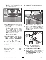
Page 46: ...ed to Step 5 to check front pressure roller If gap is more than 0 004 0 1mm then rear pressure roller must be adjusted Proceed to Step 5 to check front pressure roller before adjusting 5 Lower drum until gauge blocks just touch drum Figure 66 Example of gauge blocks placed under drums Items Needed Qty Gauge Blocks see Page 40 2 Feeler Gauge Set 1 Hex Wrench 5 32 5mm 1 Ea To adjust pressure rollers...

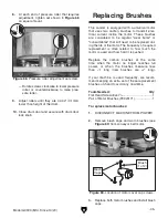
Page 47: ...nsidered to be regular wear items or consumables that will need to be replaced dur ing the life of the motor The frequency of required replacement is often related to how much the motor is used and how hard it is pushed Replace the carbon brushes at the same time when the motor no longer reaches full power or when the brushes measure less than 1 4 long new brushes are 5 8 long If your machine is u...

Page 48: ...nt at the time of printing but may not match your machine If you find this to be the case use the wiring diagram inside the motor junction box CAPACITORS INVERTERS Some capacitors and power inverters store an electrical charge for up to 10 minutes after being disconnected from the power source To reduce the risk of being shocked wait at least this long before working on capacitors EXPERIENCING DIF...

Page 49: ...ker KUOYUH 68 SERIES 9A B10K Potentiometer Hot Hot Ground 6 15 Plug 230 VAC G 13 14 23 24 ON OFF Switch KEDU KJD17B 16 M M AC AC1 Ground Hot Hot 6 15 Receptacle 230 VAC Hot Hot Ground 6 15 Plug Start Capacitor 400MFD 125VAC DRUM MOTOR CONVEYOR FEED MOTOR GND GND 230 VAC Run Capacitor 40uF 250VAC G Wiring Diagram ...

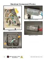
Page 50: ... 48 Model G0920 Mfd Since 10 20 READ ELECTRICAL SAFETY ON PAGE 46 Electrical Component Photos Figure 72 Start capacitor Figure 70 Switch box Figure 73 Run capacitor Figure 71 Motor junction box ...

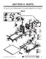
Page 51: ...6 11 70 56 56 56 154 172 46 46 46 56 56 56 56 118 118 118 93 93 91 94 91 118 56 46 95 92 82 85 111 113 134 115 133 14 16 78 84 71 84 71 142 143 82 82 112 114 154 154 47 47 157 174 20 1 20 2 20 3 20 4 20 5 20 6 20 7 20 8 20 9 20 10 20 11 171 173 153 78 55 70 55 78 55 174 Main SECTION 9 PARTS We do our best to stock replacement parts when possible but we cannot guarantee that all parts shown are ava...

Page 52: ...R 93 P0920093 DEPTH GAUGE FIXED BRACKET 20 P0920020 DRUM MOTOR 2HP 230V 1 PH 94 P0920094 DIGITAL INDICATOR 20 1 P0920020 1 MOTOR FAN COVER 95 P0920095 SWITCH BOX MOUNTING BRACKET 20 2 P0920020 2 MOTOR FAN 97 P0920097 LOCK NUT M8 1 25 20 3 P0920020 3 S CAPACITOR COVER 111 P0920111 MOTOR CORD 14G 3W 24 6 15P 20 4 P0920020 4 S CAPACITOR 400M 125V 1 3 4 X 3 1 2 112 P0920112 HEX WRENCH 6MM 20 5 P092002...

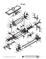
Page 53: ...236 316 247 257 234 233 225 243 245 239 240 224 244 248 346 241 238 249 237 346 238 223 237 226 246 222 247 221 230 279 230 236 253 283 255 232 231 258 205 231 232 234 234 235 235 230 230 279 246 247 316 316 252 253 247 255 257 258 281 278 282 291 285 345 282 282 285 347 347 274 349 348 271 358 247 359 337 359 360 233 205 ...

Page 54: ... 279 P0920279 BALL BEARING 6205 2RS 232 P0920232 ROLLER MOUNT RIGHT 281 P0920281 PHLP HD SCR M5 8 X 8 233 P0920233 ROLLER MOUNT LEFT 282 P0920282 FLAT WASHER 5MM 234 P0920234 COMPRESSION SPRING 0 9 X 6 3 X 25 283 P0920283 KNOB BOLT M6 1 X 10 235 P0920235 PRESSURE ROLLER 285 P0920285 LOCK WASHER 5MM 236 P0920236 DRUM DOOR HINGE 291 P0920291 PHLP HD SCR M3 5 X 6 237 P0920237 DRUM SHAFT JOINT COVER 3...

Page 55: ...467 CABINET DOOR 455 P0920455 FLAT WASHER 8MM 468 P0920468 BOTTOM PANEL 456 P0920456 LOCK WASHER 8MM 469 P0920469 RUBBER FOOT 459 P0920459 FLAT WASHER 5 16 470 P0920470 PHLP HD SCR 5 16 18 X 3 4 461 P0920461 RIGHT SIDE PANEL 471 P0920471 HEX NUT M8 1 25 462 P0920462 LEFT SIDE PANEL 475 P0920475 HEX BOLT M8 1 25 X 25 463 P0920463 FRONT PANEL 476 P0920476 CABINET DOOR LATCH HANDLE 464 P0920464 REAR ...

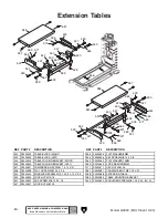
Page 56: ...K RIGHT 555 P0920555 FLAT WASHER 8MM 523 P0920523 TABLE BLOCK LEFT 556 P0920556 SET SCREW M8 1 25 X 8 524 P0920524 TABLE FOLDING BRACKET RIGHT 562 P0920562 FLAT WASHER 10MM 525 P0920525 TABLE FOLDING BRACKET LEFT 563 P0920563 LOCK WASHER 8MM 527 P0920527 COMPRESSION SPRING 1 X 10 X 21 571 P0920571 HEX NUT M8 1 25 528 P0920528 FLAT HD SCR M8 1 25 X 25 587 P0920587 CARRIAGE BOLT M8 1 25 X 20 529 P09...

Page 57: ...AIN RELIEF TYPE 1 5 8 651 P0920651 CIRCUIT BOARD CORD 14G 1W 5 603 P0920603 RESISTANCE PLATE 681 P0920681 PHLP HD SCR M5 8 X 8 604 P0920604 CONVEYOR SPEED DIAL 682 P0920682 FLAT WASHER 5MM 605 P0920605 INSULATION BOARD 683 P0920683 FLAT WASHER 4MM 606 P0920606 CIRCUIT BOARD AMP 326B 684 P0920684 PHLP HD SCR M4 7 X 20 607 P0920607 SWITCH BOX COVER 685 P0920685 LOCK WASHER 5MM 608 P0920608 FLAT HD S...

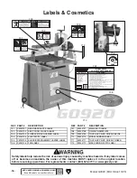
Page 58: ...TRICITY LABEL 710 P0920710 MODEL NUMBER LABEL 705 P0920705 SHOCK ENTANGLEMENT HAZARD LABEL 711 P0920711 TOUCH UP PAINT GRIZZLY GREEN 706 P0920706 FPM LABEL 712 P0920712 MAX SANDING WIDTH LABEL Safety labels help reduce the risk of serious injury caused by machine hazards If any label comes off or becomes unreadable the owner of this machine MUST replace it in the original location before resuming ...

Page 59: ...erty or for incidental contingent special or consequential damages arising from the use of our products The manufacturers reserve the right to change specifications at any time because they constantly strive to achieve better quality equipment We make every effort to ensure that our products meet high quality and durability standards and we hope you never need to use this warranty In the event you...

Page 60: ......

Reviews: