background image

-18-

Model G0926 (Mfd. Since 11/20)

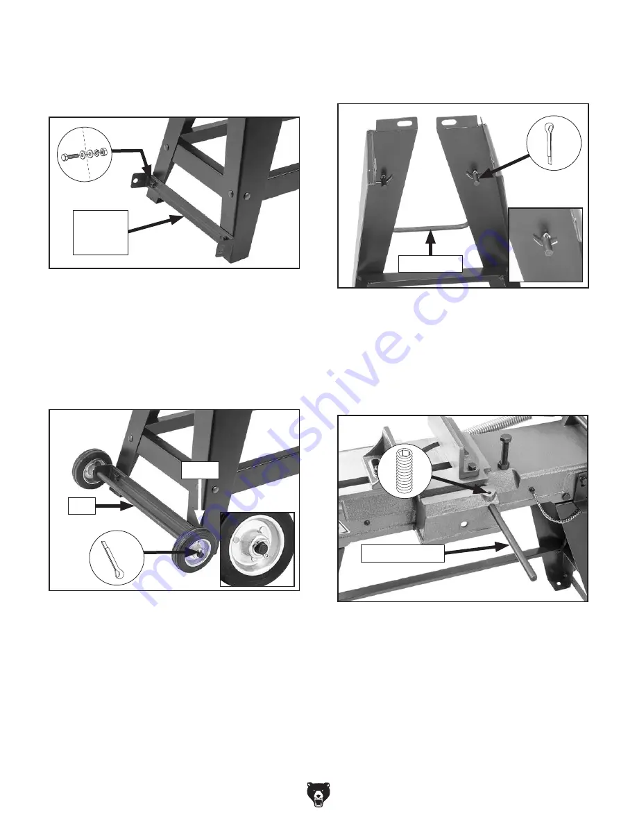
6.  Attach  wheel  mounting  bracket  to  bottom  of 

two legs with (2) M6-1 x 12 hex bolts, (4) 6mm 
flat washers, (2) 6mm lock washers, and (2) 
M6-1 hex nuts, as shown in 

Figure 13.

Figure 13. Wheel-mounting bracket attached to 

legs.

Wheel

Mounting

Bracket

Figure 14. Wheels attached to axle.

Figure 15. Cotter pins installed in handle.

7.  Slide  wheel  axle  through  holes  in  wheel-

mounting bracket (see 

Figure 14).

8.  Slide wheels onto axle on outside of mount-

ing brackets, and secure with (2) cotter pins 
(see 

Figure 14).

9.  On opposite side of stand, insert pull handle 

into  holes  shown  in 

Figure 15 and  secure 

with (2) cotter pins. 

10.  Check  to  see  if  bandsaw  is  relatively  level, 

then fully tighten all bolts and nuts.

11.  Slide  work  stop  rod  into  side  of  bandsaw, 

then  lock  it  in  place  by  tightening  set  screw 
shown in 

Figure 16.

x 2

x 2

Wheel

Axle

Pull Handle

x 2

Figure 16. Work stop rod installed.

Work Stop Rod

Summary of Contents for G0926

Page 1: ...PORTION OF THIS MANUAL MAY BE REPRODUCED IN ANY SHAPE OR FORM WITHOUT THE WRITTEN APPROVAL OF GRIZZLY INDUSTRIAL INC CS21416 PRINTED IN CHINA V1 10 20 MODEL G0926 4 X 51 2 VARIABLE SPEED METAL CUTTING...

Page 2: ...g grinding tool integrity and the usage of personal protective equipment The manufacturer will not be held liable for injury or property damage from negligence improper training machine modifications...

Page 3: ...electing Blades 23 Blade Care Break In 25 Blade Breakage 25 Chip Inspection Chart 26 Adjusting Blade Guide 27 Adjusting Feed Rate 27 Using Vise 28 Adjusting Work Stop 29 Adjusting Blade Speed 29 Blade...

Page 4: ...de every effort to be exact with the instruc tions specifications drawings and photographs in this manual Sometimes we make mistakes but our policy of continuous improvement also means that sometimes...

Page 5: ...of the controls and features shown below to better understand the instructions in this manual Blade Tension Knob Motor Vise Crank Work Stop Stand Blade Blade Tracking Mechanism Downfeed Stop Bolt Sta...

Page 6: ...justment Handle Increases feed rate when turned counterclockwise and decreases feed rate when turned clockwise Vise A Vise Crank Adjusts movable vise jaw B Movable Vise Jaw Holds workpiece against fix...

Page 7: ...1 2 in Footprint Length x Width 35 x 17 in Shipping Dimensions Type Cardboard Box Content Machine Weight 102 lbs Length x Width x Height 35 x 17 x 19 in Electrical Power Requirement 120V Single Phase...

Page 8: ...ular Height at 60 Deg 4 1 2 in Max Capacity Rectangular Width at 60 Deg 4 1 2 in Max Capacity Round at 60 Deg 4 1 2 in Construction Table Cast Iron Trunnions Cast Aluminum Upper Wheel Cast Iron Lower...

Page 9: ...proof DANGEROUS ENVIRONMENTS Do not use machinery in areas that are wet cluttered or have poor lighting Operating machinery in these areas greatly increases the risk of accidents and injury MENTAL AL...

Page 10: ...moving parts or flying debris Make sure they are properly installed undamaged and working correctly BEFORE operating machine FORCING MACHINERY Do not force machine It will do the job safer and better...

Page 11: ...they can unex pectedly move while cutting and draw the opera tor s hands into the blade causing serious per sonal injury Examples are chains cables round or oblong shaped workpieces and those with int...

Page 12: ...rsized circuit To reduce the risk of these hazards avoid over loading the machine during operation and make sure it is connected to a power supply circuit that meets the specified circuit requirements...

Page 13: ...rd size gets longer and the gauge size gets smaller higher gauge numbers indicate smaller sizes Any extension cord used with this machine must be in good condition and contain a ground wire and matchi...

Page 14: ...erly lifting machine or some of its parts To reduce this risk get help from other people and use a forklift or other lifting equipment rated for weight of this machine The following items are needed b...

Page 15: ...e will gladly replace them or for the sake of expediency replacements can be obtained at your local hardware store Box 1 Figures 5 6 Qty A Bandsaw Not Shown 1 B Chip Tray 1 C Knob Bolt M8 1 25 x 16 1...

Page 16: ...14 Model G0926 Mfd Since 11 20 Hardware Recognition Chart USE THIS CHART TO MATCH UP HARDWARE DURING THE INVENTORY AND ASSEMBLY PROCESS 5mm 5mm Flat Head Cap Screw...

Page 17: ...g gather the following Disposable rags Cleaner degreaser WD 40 works well Safety glasses disposable gloves Plastic paint scraper optional Basic steps for removing rust preventative 1 Put on safety gla...

Page 18: ...ed space allocation Physical Environment The physical environment where the machine is operated is important for safe operation and lon gevity of machine components For best results operate this machi...

Page 19: ...sawhorses or other suitable support see Figure 10 3 Attach legs to bandsaw with 8 M8 1 25 x 20 hex bolts 8mm flat washers 8mm lock wash ers and M8 1 25 hex nuts see Figure 10 Note Tighten just enough...

Page 20: ...wheel axle through holes in wheel mounting bracket see Figure 14 8 Slide wheels onto axle on outside of mount ing brackets and secure with 2 cotter pins see Figure 14 9 On opposite side of stand inser...

Page 21: ...ng the test run immediately stop the machine disconnect it from power and fix the problem BEFORE operating the machine again The Troubleshooting table in the SERVICE section of this manual can help DO...

Page 22: ...tioning correctly Proceed to Step 6 If auto tab does not switch power OFF tab is not working correctly This safety fea ture must work properly before proceeding with regular operations Call Tech Suppo...

Page 23: ...ece is stable and cutting area is free of obstructions 6 Adjusts blade guide as close to workpiece as possible 7 Adjusts spring tension for correct feed rate 8 Puts on safety glasses and respirator 9...

Page 24: ...ate your bandsaw and help you get the maximum life out of your saw blades Loosen blade tension at the end of each day to prolong blade life Operation Tips Tips for cutting Use the work stop to quickly...

Page 25: ...fferent type of blade in order to efficiently cut them Tanks Cylinders Containers Valves Etc Cutting into containers that are pressur ized or contain gasses or liquids can cause explosions fires caust...

Page 26: ...manufacturer To select correct blade pitch 1 Measure material thickness This measure ment is distance from where each tooth enters workpiece to where it exits workpiece 2 Refer to Material Width Diame...

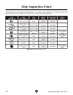
Page 27: ...in the appropriate feed rate feed pressure and blade speed and pay attention to the chip characteristics Refer to Blade Speed Chart on Page 30 and Chip Inspection Chart on Page 26 Keep your blades cle...

Page 28: ...hard thick thick hard strong thick hard strong thin straight powdery thin curled tightly hard thin thin curled short hard thick thick hard strong thick hard strong thin straight powdery thin curled ti...

Page 29: ...de guide 1 DISCONNECT MACHINE FROM POWER 2 Loosen blade guide adjustment knob shown in Figure 25 and slide blade guide as close to workpiece as possible then tighten knob Figure 26 Feed rate adjustmen...

Page 30: ...ng vise angle Hex Bolts Scale Using Vise The vise consists of a movable jaw and fixed jaw and can hold material up to 6 inches wide and be set to cut angles from 0 to 45 Tools Needed Qty Wrenches or S...

Page 31: ...iable Speed Dial The Model G0926 is equipped with a work stop for repetitive cutting operations The work stop will need to be adjusted any time it is removed or repositioned or anytime you change cutt...

Page 32: ...ed chart Material Speed FPM M Min Material Speed FPM M Min Material Speed FPM M Min Material Speed FPM M Min Carbon Steel 196 354 60 108 Tool Steel 203 62 Alloy Steel 111 321 34 98 Free Machining Stai...

Page 33: ...l Head locking pin secures headstock in down horizontal position You MUST secure headstock with locking pin before moving machine to prevent headstock unexpect edly springing up causing machine to tip...

Page 34: ...TPI Raker G5110 641 2 x 1 2 x 025 24 TPI Raker G5111 641 2 x 1 2 x 025 6 10 Variable Pitch G5112 641 2 x 1 2 x 025 8 12 Variable Pitch G5113 641 2 x 1 2 x 025 10 14 Variable Pitch G5114 641 2 x 1 2 x...

Page 35: ...ing and support tasks With 157 8 wide rollers adjustable 26 445 8 height and all steel construction make them con venient and rugged Figure 38 D2273 and D2274 single and 5 roller stands Figure 39 Reco...

Page 36: ...tamination Whenever you notice unusual resistance when closing the vise lubricate the screw shown in Figure 42 with multi purpose gear grease Figure 42 Location to lubricate vise screw Cleaning Protec...

Page 37: ...stalls bogs down in cut or is underpowered 1 Workpiece crooked vise loose or misadjusted 2 Wrong workpiece material metal or wrong blade type TPI for material 3 Gearbox at fault 4 Blade slipping on w...

Page 38: ...tension tracking requires adjustment 6 Blade guide bearings require adjustment 7 Blade weld failing 1 Secure workpiece with vise Page 28 2 Raise headstock start blade then contact workpiece 3 Use thi...

Page 39: ...g Motor Brushes This machine is equipped with a universal motor that uses two carbon brushes to transmit electri cal current inside the motor These brushes are considered to be regular wear items or c...

Page 40: ...earing heavy gloves open frame guard and remove blade from wheels x 2 5 Loosen extension guard lock knob fully raise extension guard and tighten lock knob to secure see Figure 46 To change blade 1 DIS...

Page 41: ...ten blade tension knob so blade will not slip on wheels upon start up 11 While keeping body parts away from blade and machine connect machine to power 12 Turn blade speed dial to slowest speed and bri...

Page 42: ...ng pin to keep headstock in place 4 Loosen extension guard lock knob fully raise extension guard and tight lock knob to secure see Figure 51 3 Remove 2 Phillips head screws and flat washers shown in F...

Page 43: ...NE FROM POWER 3 Loosen blade guide adjustment knob see Figure 54 and slide guide as far from front guide as it will allow then tighten knob 4 Turn blade tension knob see Figure 54 clockwise to tighten...

Page 44: ...e blade does not travel far enough to complete the cut or the blade contacts the vise table then the downfeed stop bolt will need to be adjusted Tools Needed Qty Open Ended Wrench 19mm 1 To adjust dow...

Page 45: ...justment components Eccentric Bushing Hex Nut Tools Needed Qty Machinist s Square 1 Wrench or Socket 14mm 1 Open Ended Wrench 13mm 1 Phillips Head Screwdriver 2 1 Adjusting Blade Guide Bearings The bl...

Page 46: ...rs 6 Install front blade guide guard before resum ing operation If square evenly touches both face of vise and blade no adjustment is necessary If square does not evenly touch blade when evenly touchi...

Page 47: ...t at the time of printing but may not match your machine If you find this to be the case use the wiring diagram inside the motor junction box CAPACITORS INVERTERS Some capacitors and power inverters s...

Page 48: ...Ground 110 VAC 5 15 Plug MOTOR AC1 AC2 M M RX FUSE C1 18V B10K BLADE SPEED SENSOR LINE LOAD 2017120401B S CAPACITOR ON OFF Switch KEDU HY7 20A 12A 125 250V Circuit Board PWM500C 10A 250V Circuit Break...

Page 49: ...G0926 Mfd Since 11 20 47 READ ELECTRICAL SAFETY ON PAGE 45 Electrical Component Photos Figure 64 ON OFF switch wiring Figure 61 Speed controls wiring Figure 62 Circuit board wiring Figure 63 Speed se...

Page 50: ...126 43 71 127 16 44 72 128 17 45 129 18 46 130 47 131 20 48 132 21 49 133 22 50 134 23 51 135 24 52 136 25 53 109 137 26 54 110 27 55 167 28 56 112 168 169 170 171 172 173 174 175 176 177178 179 182 1...

Page 51: ...26027 CIRCUIT BOARD PWM500C 81 P0926081 FLAT WASHER 8MM 28 P0926028 CIRCUIT BREAKER WIRE 82 P0926082 LOCK WASHER 8MM 29 P0926029 PHLP HD SCR M5 8 X 8 83 P0926083 HEX BOLT M8 1 25 X 30 30 P0926030 CIRC...

Page 52: ...926177 LOCK WASHER 5MM 131 P0926131 FEED RATE ADJUSTMENT ROD 178 P0926178 PHLP HD SCR M5 8 X 8 132 P0926132 ADJUSTMENT ROD BRACKET 179 P0926179 ON OFF SWITCH KEDU HY7 133 P0926133 FEED RATE ADJUSTMENT...

Page 53: ...926301 FLAT WASHER 8MM 311 P0926311 AXLE BRACKET 302 P0926302 CARRIAGE BOLT M8 1 25 X 16 312 P0926312 AXLE 303 P0926303 BRACE LONG 313 P0926313 COTTER PIN 2 5 X 20MM STANDARD 304 P0926304 BRACE SHORT...

Page 54: ...P 120V 1 Ph 60 Hz Full Load Current Rating 4 5A Max Round Cut 4 1 2 Dia Max Rectangular Cut 4 x 5 1 2 Blade Speeds 85 195 FPM Std Blade Length 64 1 2 Vise Angle Range 0 45 Weight 97 lbs Specifications...

Page 55: ...for incidental contingent special or consequential damages arising from the use of our products The manufacturers reserve the right to change specifications at any time because they constantly strive...

Page 56: ......
Reviews: