Model G0948 (Mfd. Since 08/21)
-21-
4. Open upper wheel cover.
5. Push blade toward fence with moderate
pressure to check if there is approximately
1
⁄
4
" deflection. If not, rotate tension adjust-
ment knob as needed until blade is properly
tensioned.
Test Run
Once assembly is complete, test run the machine
to ensure it is properly connected to power and
safety components are functioning correctly.
If you find an unusual problem during the test run,
immediately stop the machine, disconnect it from
power, and fix the problem BEFORE operating the
machine again. The
Troubleshooting table in the
SERVICE section of this manual can help.
Serious injury or death can result from
using this machine BEFORE understanding
its controls and related safety information.
DO NOT operate, or allow others to operate,
machine until the information is understood.
The test run consists of verifying the following:
1) The motor powers up and runs correctly,
and 2) the removable key on the switch works
correctly.
To adjust blade tracking:
1. DISCONNECT MACHINE FROM POWER!
2. Adjust upper and lower blade guides away
from blade, and raise upper guides all the way
up (refer to
Adjusting Blade Guide Bearings
on
Page 25 for detailed instructions).
Note: When adjusting the blade tracking for
the test run in this procedure, the blade must
have approximately the same amount of ten-
sion as when under operating conditions.
After the test run is successfully completed,
you will be instructed on how to more accu-
rately tension the blade for optimum results.
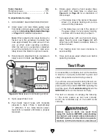
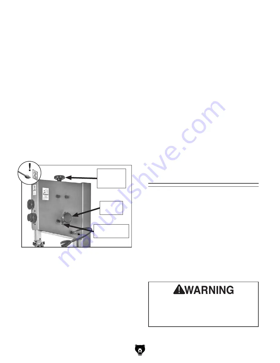
3. Rotate tension adjustment knob clockwise to
apply tension to blade (see
Figure 22).
6. Rotate upper wheel by hand several times
and watch how blade rides on wheel (see
Figure 20 on Page 20 for an illustration of
this concept).
— If the blade rides in the center of the upper
wheel, it is properly tracking and you are
done with this procedure.
— If the blade does not ride in the center of
the upper wheel, it is not properly tracking;
continue with the next step to adjust it.
7. Spin upper wheel with one hand and slowly
adjust tracking knob (see
Figure 22) with
other hand until blade consistently tracks in
center of wheel.
8. Turn tracking knob lock lever clockwise to
secure setting.
9. Close and secure upper wheel cover before
operating bandsaw.
Figure 22. Blade tension and tracking controls.
Tracking Knob
Lock Lever
Tracking
Knob
Tension
Adjustment
Knob
Tool(s) Needed
Qty
Protective Gloves..........................................1 Pr.
Hex Wrenches 4, 5mm ................................1 Ea.
Summary of Contents for G0948
Page 68: ......

