background image

-52-

Model G0948 (Mfd. Since 08/21)

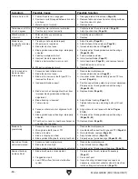
Replacing Belt

Item(s) Needed 

Qty

Hex Wrench 6mm .............................................. 1
Retaining Ring Pliers ......................................... 1
Heavy Leather Gloves ..................................1 Pr.
Replacement Belt (Part # P0948105) ................ 1

To replace belt:

1.  DISCONNECT MACHINE FROM POWER!

2.  Put  on  heavy  leather  gloves  and  remove 

blade  from  machine  (refer  to 

Removing/

Installing Blade on Page 39).

3.  Loosen  motor  mount  cap  screws  (see 

Figure 67 on Page 51).

4.  Pivot motor to the right (as viewed from back 

of bandsaw) to release belt tension.

5.  Open  lower  wheel  cover  and  remove  belt 

from motor pulley.

To ensure optimum power transmission from the 
motor to the blade, the belt must be in good condi-
tion and be properly tensioned.

Replace the belt if it shows signs of cracking, fray-
ing, or excessive wear.

7.  Install new belt on both pulleys, and then re-

install wheel and retaining ring.

8.  Properly  tension  belt,  as  instructed  in 

Adjusting Belt Tension on Page 51.

9.  Install blade, properly track and tension blade 

(see 

Pages  20  &  22),  and  adjust  support 

bearings  and  guide  bearings  (see 

Pages 

2425).

6.  Remove  external  retaining  ring  from  lower 

wheel  shaft  (see 

Figure  68)  and  remove 

lower wheel.

Figure 68. Belt change components inside lower 

wheel compartment.

External 

Retaining Ring

Belt

Summary of Contents for G0948

Page 1: ...r models manufactured since 08 21 COPYRIGHT SEPTEMBER 2021 BY GRIZZLY INDUSTRIAL INC WARNING NO PORTION OF THIS MANUAL MAY BE REPRODUCED IN ANY SHAPE OR FORM WITHOUT THE WRITTEN APPROVAL OF GRIZZLY IN...

Page 2: ...g grinding tool integrity and the usage of personal protective equipment The manufacturer will not be held liable for injury or property damage from negligence improper training machine modifications...

Page 3: ...ating Miter Gauge 29 SECTION 4 OPERATIONS 30 Operation Overview 30 Basic Functions of a Bandsaw 31 Workpiece Inspection 31 Setting Upper Blade Guide Height 32 Tilting Table 32 Choosing Blades 34 Blade...

Page 4: ...ade every effort to be exact with the instruc tions specifications drawings and photographs in this manual Sometimes we make mistakes but our policy of continuous improvement also means that sometimes...

Page 5: ...opped c Maintain proper adjustment of blade tension blade guides and thrust bearings d Adjust upper blade guide to just clear workpiece e Hold workpiece firmly against table Upper Wheel Cover Blade Te...

Page 6: ...B LED Work Light ON OFF Switch Turns light ON and OFF Illuminates cutting area for better visibility Figure 3 Fence mounted in horizontal position Horizontal Position Allows Upper Blade Guide to Be Ad...

Page 7: ...g knob J Trunnion w Table Tilt Scale Functions as a tilting base for table Graduated in degrees from 0 45 for setting bevel angle K Table Tilt Lock Lever Secures table tilt angle setting L Table Tilt...

Page 8: ...lectrical Power Requirement 120V Single Phase 60 Hz Full Load Current Rating 3 5A Minimum Circuit Size 15A Connection Type Cord Plug Power Cord Included Yes Power Cord Length 72 in Power Cord Gauge 18...

Page 9: ...nstruction Materials Table Cast Aluminum Trunnion Steel Fence Aluminum Base Stand Steel Frame Body Steel Wheels Cast Aluminum Tire Rubber Wheel Cover Steel Paint Type Finish Urethane Other Related Inf...

Page 10: ...d proof DANGEROUS ENVIRONMENTS Do not use machinery in areas that are wet cluttered or have poor lighting Operating machinery in these areas greatly increases the risk of accidents and injury MENTAL A...

Page 11: ...moving parts or flying debris Make sure they are properly installed undamaged and working correctly BEFORE operating machine FORCING MACHINERY Do not force machine It will do the job safer and better...

Page 12: ...Always keep workpiece flat and firm against table fence when cutting to avoid loss of control If necessary use a jig or other work holding device WORKPIECE MATERIAL This machine is intended for cutti...

Page 13: ...sized circuit To reduce the risk of these hazards avoid over loading the machine during operation and make sure it is connected to a power supply circuit that meets the specified circuit requirements...

Page 14: ...ord size gets longer and the gauge size gets smaller higher gauge numbers indicate smaller sizes Any extension cord used with this machine must be in good condition and contain a ground wire and match...

Page 15: ...16 1 Straightedge 1 Ruler 1 Shims As Needed Machinist s Square 1 Level 18 1 Dust Collection System 1 Dust Hose 2 3 or 4 1 Hose Clamps 2 3 or 4 2 This machine presents serious injury hazards to untrain...

Page 16: ...auge 1 D Table w Insert 1 E Fence Rail 1 F Wing Bolts M8 1 25 x 18 4 G Push Stick 1 H Open End Wrench 10 x 13mm 1 I Hex Wrenches 3 4 5 6mm 1 Ea J Rubber Feet 4 K Stand Braces Long 2 L Stand Braces Sho...

Page 17: ...Model G0948 Mfd Since 08 21 15 Hardware Recognition Chart USE THIS CHART TO MATCH UP HARDWARE DURING THE INVENTORY AND ASSEMBLY PROCESS 5mm 5mm Flat Head Cap Screw...

Page 18: ...s work tables or other machinery when establishing a location for this machine in the shop Below is the minimum amount of space needed for the machine Placement Location Assembly LACERATION HAZARD Ban...

Page 19: ...level side to side and front to back then tighten all fasteners installed in Steps 2 5 7 Remove 4 pre installed M6 1 x 10 hex bolts and 6mm flat washers from base of table and loosen 2 shoulder screw...

Page 20: ...em bly then place machinist s square flat on table against side of blade see Figure 16 10 Loosen table lock lever and tilt table until square is flat against side of blade as illus trated in Figure 16...

Page 21: ...chine creates a lot of wood chips dust during operation Breathing airborne dust on a regular basis can result in perma nent respiratory illness Reduce your risk by wearing a respirator and capturing t...

Page 22: ...a properly tracking blade naturally tracks at the center of the wheel see Figure 20 The bandsaw wheels must be aligned for optimal machine performance Properly aligned wheels are parallel and coplanar...

Page 23: ...es all the way up refer to Adjusting Blade Guide Bearings on Page 25 for detailed instructions Note When adjusting the blade tracking for the test run in this procedure the blade must have approximate...

Page 24: ...ade life and making other bandsaw adjustments However a properly tensioned blade will not compensate for cutting problems caused by excessive feed rate hardness variations between workpieces and impro...

Page 25: ...25 The Flutter Method The deflection method is much more subjective than the flutter method Each blade will deflect differently and every user will determine what moderate pressure means The following...

Page 26: ...ket 10mm 1 Hex Wrench 4mm 1 Feeler Gauge 0 016 1 To adjust lower support bearing 1 DISCONNECT MACHINE FROM POWER 2 Loosen button head cap screw see Figure 26 Adjusting Lower Support Bearing 3 Position...

Page 27: ...ck of the blade Blade teeth are angled out slightly protrud ing wider than the blade thickness this is known as blade tooth set see Figure 29 If teeth contact guide bearings during oper ation damage m...

Page 28: ...Adjusting Lower Blade Guide Bearings To adjust lower blade guide bearings 1 DISCONNECT MACHINE FROM POWER 2 Loosen guide block cap screw see Figure 31 then laterally position guide bearings just behin...

Page 29: ...front and back of table it must be adjusted proceed to Step 5 Figure 32 Example of placing a straightedge along blade and measuring to miter slot Miter Slot Blade Adusting Miter Slot Parallelism 5 Lo...

Page 30: ...e Adjusting Miter Slot Parallelism on Page 27 for instructions Aligning Fence 3 Determine which trunnion is on low side of table then remove two hex bolts see Figure 33 on Page 26 from low trunnion 4...

Page 31: ...d in the miter slot Tool s Needed Qty Phillips Screwdriver 2 1 Square 1 3 Loosen lock knob on miter gauge and adjust face flush with edge of square 4 Tighten lock knob and verify square rests flush an...

Page 32: ...ck to feed narrow workpieces 9 Stops bandsaw then dust collector The purpose of this overview is to provide the nov ice machine operator with a basic understanding of how the machine is used during op...

Page 33: ...tting natural and man made wood prod ucts laminate covered wood products and some plastics Cutting drywall or cementious backer board creates extremely fine dust and may reduce the life of the bearing...

Page 34: ...ting Table The table can be tilted from 0 45 right to make beveled cuts A table tilt scale with indicator is provided on the trunnion and a positive stop is provided for quickly returning the table ba...

Page 35: ...Loosen table tilt lock lever and tilt table to approximately 10 right 3 Loosen positive stop jam nut and lower posi tive stop bolt so it will not interfere with the following steps 4 Place a machinis...

Page 36: ...ing Use the chart in Figure 42 to determine the correct blade for curve cutting Determine the smallest radius curve that will be cut on your workpiece and use the corre sponding blade width Straight C...

Page 37: ...aterial Raker Skip Hook Figure 43 Main blade tooth styles Tooth Pitch Measured as TPI teeth per inch tooth pitch determines the number of teeth More teeth per inch fine pitch will cut slower but smoot...

Page 38: ...Blade Material Bandsaw blades must meet two requirements flexibility and hardness The flexibility of a blade allows it to travel on the wheel as a band while hardness allows the teeth to cut and hold...

Page 39: ...M Crosscutting Thin Stock R H S F Crosscutting Thick Stock R H S M Crosscutting Round Stock R H S F M R H S F M Miter Cut R H S F M Tenons R H S M R H S M Sharp Curves R H S F Gradual Curves R H S F M...

Page 40: ...piece thickness The general rule of thumb is to have no less than two teeth in contact with the workpiece at all times during cutting Blade Care Break In Blade Care A bandsaw blade is a thin piece of...

Page 41: ...T MACHINE FROM POWER 2 Slide blade through table slot ensuring that teeth are pointing down toward table Note If the teeth will not point downward in any orientation the blade is inside out Remove the...

Page 42: ...rent pulley grooves Keep in mind cutting results are not just related to blade speed Other factors include the type of workpiece the blade being used for the operation and the feed rate Use the chart...

Page 43: ...ick when ripping narrow pieces Failure to follow these warnings may result in amputation or laceration injuries Crosscutting is the process of cutting across the grain of wood For plywood and other pr...

Page 44: ...n proceed to the longer cuts Relief cuts reduce the chance of the blade being pinched or twisted Relief cuts are cuts made through the waste portion of the workpiece and are stopped at the layout line...

Page 45: ...r that will not interfere with cutting Hot glue on the edges works well as do brad nails through the waste portion Be careful not to cut into the brads or you may break the blade 3 Lay out the shape y...

Page 46: ...r H3635 Cartridge Filter Pair P100 If you work around dust everyday a half mask respirator can be a lifesaver Also compatible with safety glasses H3635 H3631 Basic Eye Protection T20501 Face Shield Cr...

Page 47: ...st Gate 4 W1053 Anti Static Grounding Kit We ve hand picked a selection of dust collection components commonly needed to connect your new machine to basic dust collection Figure 58 Dust collection acc...

Page 48: ...nal rings Includes 4 bent and 4 straight pliers made of heat treated steel in sizes 51 2 to 9 The 5 and 6 pliers have a 1 2mm 047 tip the 71 2 and 8 pliers have a 1 8mm 07 tip and the 81 2 and 9 plier...

Page 49: ...rn or damaged wires Any other unsafe condition Monthly Check belt for tension damage or wear Remove blade and thoroughly clean all built up sawdust from the rubber tires on the wheels Clean vacuum dus...

Page 50: ...sconnected corroded connections 7 Replace switch 8 Replace motor Machine stalls or is underpowered 1 Dull blade 2 Workpiece material unsuitable for machine 3 Feed rate cutting speed too fast 4 Workpie...

Page 51: ...tracking Page 20 7 Adjust blade guide bearings properly so guides cannot contact teeth during operation Pages 24 25 8 Replace or re install tire 9 Align table miter slot and fence with blade Pages 27...

Page 52: ...per blade guide support bearing adjustment 6 Blade tracking is incorrect 7 Table is loose 8 Fence or miter slot out of alignment with blade 9 Blade guides support bearings improperly adjusted 10 Tooth...

Page 53: ...as viewed from back of machine until you feel moderate tension then tighten both cap screws 4 Check belt tension If necessary repeat Steps 2 3 until there is approximately 3 8 deflection in belt 5 Clo...

Page 54: ...belt from motor pulley To ensure optimum power transmission from the motor to the blade the belt must be in good condi tion and be properly tensioned Replace the belt if it shows signs of cracking fr...

Page 55: ...el but upper or lower wheel is not coplanar with the other wheel Move the upper wheel in or out Upper wheel is not vertically aligned with lower wheel Use blade tracking knob to tilt upper wheel Lower...

Page 56: ...el AdjustingLowerWheelShaftPosition If the lower wheel is tilted laterally side to side perform the following procedure to make it copla nar with the upper wheel There are four adjustment bolts with h...

Page 57: ...il or marker to indicate measuring locations see Figure 73 Note Marking the wheels ensures more accurate results in case there are irregulari ties in the wheels Requires lateral adjustment Viewed From...

Page 58: ...y wander off the cut line when sawing as shown in Figure 75 This is called blade lead Figure 75 Example of blade lead Item s Needed Qty Hex Wrench 4mm 1 Scrap Wood 3 4 x 3 x 17 1 Clamp 4 1 1 Make sure...

Page 59: ...with the tire Tool s Needed Qty Wrench or Socket 13mm 1 To adjust wheel brush 1 DISCONNECT MACHINE FROM POWER 2 Open lower wheel cover 3 On rear of machine loosen acorn nut that secures wheel brush i...

Page 60: ...t at the time of printing but may not match your machine If you find this to be the case use the wiring diagram inside the motor junction box CAPACITORS INVERTERS Some capacitors and power inverters s...

Page 61: ...y LED Driver LED 5V700 Hopestar 120V 5 5W E337681 Ground Ground 120V Motor 5 15 Plug 120VAC Ground Hot Neutral Ground Start Capacitor CBB60 35uF 350VAC LED Light Nanjing 12V 1W DKLD AN 18 250V 6A Ligh...

Page 62: ...08 21 READ ELECTRICAL SAFETY ON PAGE 58 Electrical Components Figure 78 Start capacitor wiring Start Capacitor Figure 79 Work light wiring Figure 77 ON OFF switch wiring LED Driver LED Light ON OFF S...

Page 63: ...23 24 25 26 22 18 8 7 40 41 42 44 43 45 46 47 48 52 53 59 58 54 57 31 30 29 28 32 33 34 35 36 37 38 39 27 51 50 49 56 55 172 173 174 171 175 170 164 165 166 167 169 168 20 18 19 16 16 16 17 116 112 11...

Page 64: ...P0948024 LOCK NUT M6 1 76 P0948076 CAP SCREW M5 8 X 6 25 P0948025 SPACER 77 P0948077 CONNECTING SHAFT 26 P0948026 CAP SCREW M6 1 X 16 78 P0948078 SUPPORT BLOCK 27 P0948027 FRAME 79 P0948079 SET SCREW...

Page 65: ...SQUARE NUT M5 8 116 P0948116 POWER CORD 18G 3W 72 5 15P 157 P0948157 SPACER 117 P0948117 KNOB BOLT M8 1 25 X 18 D72 WING 158 P0948158 CAP SCREW M5 8 X 10 118 P0948118 TABLE INSERT 159 P0948159 SPRING...

Page 66: ...ng and guides 9 Keep upper guide adjusted to just clear the workpiece 10 Hold workpiece firmly against table to maintain control 11 Only run saw with wheel covers closed and all guards in place 12 Nev...

Page 67: ...rty or for incidental contingent special or consequential damages arising from the use of our products The manufacturers reserve the right to change specifications at any time because they constantly...

Page 68: ......

Reviews: