Model G0948 (Mfd. Since 08/21)
-27-
Aligning Table
To ensure cutting accuracy, the table should be
aligned so that the miter slot is parallel to the
bandsaw blade.
Item(s) Needed
Qty
Precision Straightedge ...................................... 1
Precision Ruler .................................................. 1
Square ............................................................... 1
Hex Wrench 6mm .............................................. 1
Wrench or Socket 10mm ................................... 1
Shims ................................................. As Needed
Adjusting Miter Slot Parallelism
1. Make sure blade is tracking properly and cor-
rectly tensioned (refer to
Pages 20 and 22).
2. DISCONNECT MACHINE FROM POWER!
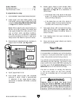
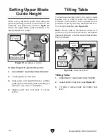
3. Place straightedge along blade so it barely
touches both front and back of blade without
going across a tooth (see
Figure 32).
4. Measure distance between straightedge and
miter slot (see
Figure 32). Distance should
be same at front and back of table.
— If distance is same at front and back of
table, no adjustment is necessary.
— If distance is not same at front and back
of table, it must be adjusted; proceed to
Step 5.
Figure 32. Example of placing a straightedge
along blade and measuring to miter slot.
Miter
Slot
Blade
Adusting Miter Slot Parallelism
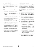
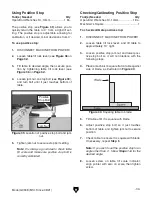
5. Loosen trunnion hex bolts that secure table
(see
Figure 33).
6. Adjust table until distance between straight-
edge and miter slot is same at front and back
of table.
7. Taking care not to move table, tighten trun-
nion hex bolts, then repeat
Step 4 to verify
adjustment.
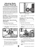
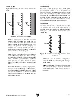
Figure 34. Squaring back of blade and table.
Blade
Square
Table
Adjusting Table Perpendicular to
Blade
1. DISCONNECT MACHINE FROM POWER!
2. Place a square on table and against back
of blade, as illustrated in
Figure 34. Table
should be perpendicular to back of blade.
— If the table is perpendicular to the back
of the blade, no adjustment is necessary;
proceed to
Aligning Fence on Page 28.
— If the table is not perpendicular to the back
of the blade, you must shim the table; pro-
ceed to
Step 3.
Figure 33. Location of trunnion hex bolts.
x 4
Summary of Contents for G0948
Page 68: ......


