-54-
Model G0949G (Mfd. Since 01/22)
5. Install 80T gear on L shaft.
6. Install 55T gear on Z3/Z4 shaft in Z3 position.
7. Install 40T gear on Z3/Z4 shaft in Z4 position.
8. Install 70T gear on Z1/Z2 shaft in Z2 position.
9. Install 40T gear on Z3/Z4 shaft in Z4 position.
10. Loosen mounting hardware necessary and
adjust backlash to between 0.002"–0.004".
Tighten hardware once adjustment is com-
plete and gears are meshed correctly.
11. Re-install end gear cover.
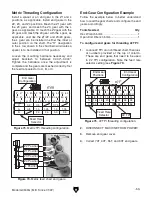
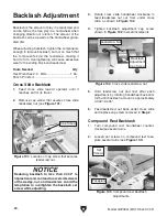
Figure 76. End gear placement.
Z1 (Outer)
and Z2
(Inner)
Positions
Z3 (Inner)
and Z4
(Outer)
Positions
L Position
The following subsections will describe how to
use the threading controls and charts to set up the
lathe for a threading operation. If you are unfamil-
iar with the process of cutting threads on a lathe,
we strongly recommend that you read books,
review industry trade magazines, or get formal
training before attempting any threading projects.
Threading
Headstock Threading Configuration
The threading charts on the headstock face (see
Figure 77) display settings for inch and metric
threading.
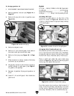
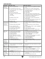
The lathe is now set up to cut 22 TPI threads.
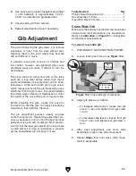
Figure 78. Feed direction and feed/thread
selector settings for 22 TPI.
Feed/
Thread
Selector
Feed
Direction
Selector
Feed
Rate
Selector
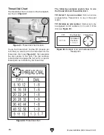
Figure 77. 22 TPI threading configuration.
B
A
C
8
16
32
9
18
36
10
20
40
11
22
44
12
24
48
13
26
52
14
28
56
90
45 40
70
H
H
H
H
H
H
H
H
H
H
H
H
H
80
80
80
80
60
65
60
70
70
70
55
80
40
40
30
40 70
75
75
50
50
55 50
60
Z Z
Z
Z
L
H
Feed Rate
Selector
22 TPI
End Gear
Configuration
End Gear
Positions
Using the controls on the lathe, follow the exam-
ple below to understand how to set up the lathe
for the desired threading operation.
To set levers for 22 TPI:
1. Locate 22 TPI on inch threading chart shown
in
Figure 78.
2. Install gears as instructed in End-Gear
Configuration Example on Page 53.
3. On inch thread chart, locate correct position
of feed rate selector. Shift lever to position
A,
as shown in
Figure 78.
4. Position feed direction selector to left, and
feed/thread selector to right, as shown in
Figure 78.
Summary of Contents for G0949G
Page 108: ......


