background image

model g1183/g1276 (mfg. since 3/10)

-13-

Extension Cords

We  do  not  recommend  using  an  extension  cord 
with  this  machine.  If  you  must  use  an  extension 
cord, only use it if absolutely necessary and only 
on a temporary basis.

Extension  cords  cause  voltage  drop,  which  may 
damage electrical components and shorten motor 
life. Voltage drop increases as the extension cord 
size gets longer and the gauge size gets smaller 
(higher gauge numbers indicate smaller sizes).

Any extension cord used with this machine must 
contain  a  ground  wire,  match  the  required  plug 
and  receptacle,  and  meet  the  following  require-
ments:

Minimum Gauge Size ...........................12 AWG

Maximum Length (Shorter is Better).......50 ft.

Voltage Conversion

the  voltage  conversion  must  be  performed 
by  an  electrician  or  qualified  service  personnel. 
make  sure  the  power  supply  circuit  for  the  new 
voltage meets the specified circuit requirement on 

page 11

.

To convert the machine to 220V:

1.

  disConneCt maChine From poWer!

2.

  replace the 5-15 plug on the power cord with 

a 6-15 plug.

3.

  re-wire the motor as illustrated in the wiring 

diagram on 

page 39

.


Note: 

If  the  diagram  included  on  the  motor 

conflicts  with  the  one  in  this  manual,  the 
motor  may  have  changed  since  the  manual 
was printed. Use the diagram provided on the 
motor.

Summary of Contents for G1183

Page 1: ... Manual Copyright 1989 By Grizzly Industrial Inc Revised APRIL 2011 TS Warning No portion of this manual may be reproduced in any shape Or form without the written approval of Grizzly Industrial inc For models manufactured SINCE 3 10 0335 printed IN TAIWAN ...

Page 2: ...ng grinding tool integrity and the usage of personal protective equipment The manufacturer will not be held liable for injury or property damage from negligence improper training machine modifications or misuse Some dust created by power sanding sawing grinding drilling and other construction activities contains chemicals known to the State of California to cause cancer birth defects or other repr...

Page 3: ...ght Load 17 Space Allocation 17 Physical Environment 17 Electrical Installation 17 Lighting 17 Mounting 18 Assembly 18 Table Gap Adjustment 20 Checking Belt Tracking 21 Dust Collection 22 Power Connection 22 Connecting Power 22 Disconnecting Power 23 Test Run 23 SECTION 4 OPERATIONS 24 Operation Overview 24 Table Tilt 25 Sandpaper Selection 26 Sanding Belt Replacement 26 Disc Sandpaper Replacement...

Page 4: ... instructions specifications drawings and photographs of the machine we used when writing this manual However sometimes we still make an occasional mistake Also owing to our policy of continuous improve ment your machine may not exactly match the manual If you find this to be the case and the dif ference between the manual and machine leaves you in doubt check our website for the latest manual upd...

Page 5: ...ing belt for removal installa tion C Sanding Belt Table Angle Scale Displays the tilt angle of the belt table D Sanding Belt Table Lock Lever Locks the belt table in place after changing the tilt angle E Sanding Disc Table Angle Scale Displays the tilt angle of the disc table F Sanding Disc Table Lock Knob 1 of 2 Locks the disc table in place after changing the tilt angle G ON OFF Switch Turns the...

Page 6: ... x 16 1 2 x 29 1 2 in Footprint Length x Width 16 1 2 x 14 in Shipping Dimensions Type Cardboard Content Machine Weight 148 lbs Length x Width x Height 30 x 28 x 18 in Electrical Power Requirement 110V 220V Single Phase 60 Hz Prewired Voltage 110V Full Load Current Rating 12A at 110V 6A at 220V Minimum Circuit Size 15A Switch Push Button Switch Voltage 110V Cord Length 5 ft Cord Gauge 14 gauge Plu...

Page 7: ... 5000 FPM Belt Arm Tilt 0 90 deg Height Belt Arm Horizontal 14 1 2 in Height Belt Arm Vertical 29 1 2 in Belt Release Quick Release Drive Roller Type Aluminum Drive Roller Length 6 1 4 in Drive Wheel Diameter 5 in Idler Roller Type Aluminum Idler Roller Length 6 1 4 in Idler Roller Diameter 3 1 2 in Spindle Info Arbor Size 3 4 in Total Arbor Length 6 in Disc Info Sanding Disc Diameter 12 in Sandin...

Page 8: ... 2 x 16 1 2 x 29 1 2 in Footprint Length x Width 17 x 14 in Shipping Dimensions Type Cardboard Content Machine Weight 150 lbs Length x Width x Height 30 x 28 x 18 in Electrical Power Requirement 110V 220V Single Phase 60 Hz Prewired Voltage 110V Full Load Current Rating 12A at 110V 6A at 220V Minimum Circuit Size 15A Switch Push Button Switch Voltage 110V Cord Length 5 ft Cord Gauge 14 gauge Plug ...

Page 9: ... 2500 FPM Belt Arm Tilt 0 90 deg Height Belt Arm Horizontal 14 1 2 in Height Belt Arm Vertical 29 1 2 in Belt Release Quick Release Drive Roller Type Aluminum Drive Roller Length 6 1 4 in Drive Wheel Diameter 5 in Idler Roller Type Aluminum Idler Roller Length 6 1 4 in Idler Roller Diameter 3 1 2 in Spindle Info Arbor Size 3 4 in Total Arbor Length 6 in Disc Info Sanding Disc Diameter 12 in Sandin...

Page 10: ...r operate under the influence of drugs or alcohol when tired or when distracted OWNER S MANUAL Read and understand this owner s manual BEFORE using machine Untrained users can be seriously hurt EYE PROTECTION Always wear ANSI approved safety glasses or a face shield when operating or observing machinery to reduce the risk of eye injury or blindness from flying particles Everyday eyeglasses are not...

Page 11: ...DIRECTION Unless otherwise noted feed work against the rotation of blades or cutters Feeding in the same direction of rotation may pull your hand into the cut FORCING MACHINERY Do not force machine It will do the job safer and better at the rate for which it was designed GUARDS COVERS Guards and covers can protect you from accidental contact with moving parts or flying debris Make sure they are pr...

Page 12: ... is applied DISC DIRECTION Only sand on the downward moving left side of the sanding disc Sanding on the upward moving right side of the sanding disc forces the operator to rely only on hands rather than the table for support which increases the risk of workpiece kick out and impact abrasion injuries AVOIDING ENTANGLEMENT Becoming entan gled in the moving parts of this machine can cause pinching a...

Page 13: ...and make sure it is connected to a power supply circuit that meets the requirements in the following section For your own safety and protection of property consult a qualified electrician if you are unsure about wiring practices or electrical codes in your area Note The circuit requirements listed in this man ual apply to a dedicated circuit where only one machine will be running at a time If this...

Page 14: ...gure 7 Typical 6 15 plug and receptacle Grounding Prong Current Carrying Prongs 6 15 PLUG GROUNDED 6 15 RECEPTACLE Serious injury could occur if you connect the machine to power before completing the setup process DO NOT connect to power until instructed later in this manual For 110V operation This machine is equipped with a power cord that has an equipment ground ing wire and a grounding plug see...

Page 15: ...match the required plug and receptacle and meet the following require ments Minimum Gauge Size 12 AWG Maximum Length Shorter is Better 50 ft Voltage Conversion The voltage conversion MUST be performed by an electrician or qualified service personnel Make sure the power supply circuit for the new voltage meets the specified circuit requirement on Page 11 To convert the machine to 220V 1 DISCONNECT ...

Page 16: ... Collection System 1 Dust Hose 3 1 Hose Clamp 3 1 Dust Hose 21 2 1 Hose Clamp 21 2 1 Needed for Setup Your machine was carefully packaged for safe transportation Remove the packaging materials from around your machine and inspect it If you discover the machine is damaged please imme diately call Customer Service at 570 546 9663 for advice Save the containers and all packing materials for possible ...

Page 17: ... this list check the mounting location on the machine or the packaging materials Sometimes parts are pre installed for shipping or they become hidden by packaging materials Shipping Inventory Figure 8 Qty A Sander Assembly 1 B Sanding Belt Table 1 C Belt Table Trunnion 1 D Dust Port 3 1 E Disc Table w Trunnions 1 F Miter Gauge Assembly 1 G Dust Hose Assembly 2 1 2 1 H Hardware Not Shown Quick Rele...

Page 18: ... glasses disposable gloves Plastic paint scraper optional Basic steps for removing rust preventative 1 Put on safety glasses 2 Coat the rust preventative with a liberal amount of cleaner degreaser then let it soak for 5 10 minutes 3 Wipe off the surfaces If your cleaner degreas er is effective the rust preventative will wipe off easily If you have a plastic paint scraper scrape off as much as you ...

Page 19: ...tion Physical Environment The physical environment where your machine is operated is important for safe operation and the longevity of its components For best results operate this machine in a dry environment that is free from excessive moisture hazardous chemi cals airborne abrasives or extreme conditions Extreme conditions for this type of machinery are generally those where the ambient temperat...

Page 20: ... setup Machine Base Workbench Lag Screw Flat Washer Figure 11 Example of a direct mount setup Another option for mounting is a Direct Mount where the machine is simply secured to the work bench with a lag screw and flat washer To assemble the sander 1 Unthread the screw cap on the sanding belt table lock lever remove the lever then unthread the lock bolt and flat washer from the sander see Figure ...

Page 21: ...he sanding belt housing with the 2 1 4 20 x 1 2 Phillips head screws as shown in Figure 15 6 Loosen the sanding belt pivot cap screw shown in Figure 16 rotate the sanding belt assembly to the vertical position then re tighten the cap screw to hold it place 7 Attach the dust hose assembly to the lower disc bracket with the 2 10 24 x 3 8 flange screws as shown in Figure 17 Figure 15 Sanding belt dus...

Page 22: ...stment by slid ing the miter gauge into the table T slot then positioning a 90 square flat against the miter face and up against the sanding surface as shown in Figure 20 Figure 20 Positioning the miter gauge and square for aligning the table If the square is flat against the miter face and the sanding surface and the table is no more than 1 16 away from the sandpaper for both tables no adjustment...

Page 23: ...aral lelism The upper belt roller is designed with a slight crown in the middle and the belt platen should be even with the highest point of this crown to ensure proper belt tracking Additionally the upper roller should be parallel to the lower roller so that the sanding belt rides evenly in the middle of the rollers To check the belt tracking 1 DISCONNECT SANDER FROM POWER 2 Put on heavy leather ...

Page 24: ...w to cal culate these variables is beyond the scope of this manual Consult an expert or purchase a good dust collection how to book Figure 24 Dust hoses attached To connect the sander to the dust collection system 1 Fit the dust hoses over both dust ports as shown in Figure 24 and secure them in place with hose clamps 2 Tug the hoses to make sure they do not come off Note A tight fit is necessary ...

Page 25: ...urn the machine ON 4 Listen to and watch for abnormal noises or actions The machine should run smoothly with little or no vibration or rubbing noises Strange or unusual noises should be inves tigated and corrected before operating the machine further Always disconnect the machine from power when investigating or correcting potential problems 5 Turn the machine OFF Power Connection After you have c...

Page 26: ... Makes sure the sandpaper is in good condi tion and properly mounted 4 Puts on safety glasses and a respirator and turns the dust collection system ON 5 Starts the sander 6 Makes sure the sanding belt is tracking prop erly 7 Feeds the workpiece slowly into the sand paper while maintaining firm pressure on the workpiece against the table or miter gauge Keeps hands and fingers away from the mov ing ...

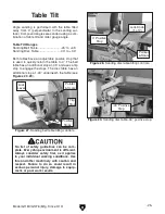
Page 27: ...ngage the stops The disc table has an additional stop at 40 underneath the table see Figures 27 29 Figure 27 Sanding belt table tilting controls Positive Stops Flip Stop Pointer Scale Lock Lever Figure 28 Sanding disc table tilting controls Pointer Scale 0 Positive Stop Lock Knob 1 of 2 Figure 29 Sanding disc table 40 positive stop 40 Positive Stop No list of safety guidelines can be com plete Eve...

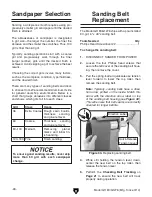
Page 28: ...ness sanding and glue removal 80 100 Medium Removing planer marks and initial fin ish sanding 120 180 Fine Finish sanding To ensure good sanding results never skip more than 50 grit with each sandpaper change The Model G1183 G1276 ships with a pre installed 80 grit 6 x 48 sanding belt Tools Needed Qty Phillips Head Screwdriver 2 1 To change the sanding belt 1 DISCONNECT SANDER FROM POWER 2 Loosen ...

Page 29: ...e 31 for an example Figure 31 Example photo of installing the sandpaper disc 5 Position the exposed adhesive on the upper half of the aluminum disc that extends above the table Once it is positioned evenly across the disc press the adhesive onto the sur face 6 Rotate the disc so the lower half is above the table Peel off the other half of the protective paper then press the remaining sandpaper aga...

Page 30: ...shown in Figure 36 Figure 36 Positioning the sanding belt assembly Pivot Cap Screw Figure 34 Example of compound angle sanding Figure 35 Example of round workpiece sanding If the sanding belt or table unexpectedly moves when sanding your hands could slip and contact the moving sandpaper result ing in abrasion injuries Always make sure the table lock lever and the sanding belt pivot cap screw are t...

Page 31: ...cal face and edge sanding Sanding workpieces with high resin content or with applied finishes can quickly con taminate the sandpaper beyond the point where it can be properly cleaned This will produce poor sanding results In this case use a different workpiece remove the applied finishes or frequently clean replace the sandpaper strip Always sand with the workpiece supported by the table Relying o...

Page 32: ...oxide sanding discs are manufac tured in ISO 9002 factories to ensure the highest quality and are available in packs of two Grit Model 60 Grit G1220 80 Grit G4255 100 Grit G1221 120 Grit G4256 150 Grit G1222 180 Grit G4257 220 Grit G4258 G2405 Safety Push Blocks Made of high impact molded plastic these safety push blocks have a layer of friction rubber on the bottom that grabs your workpiece as yo...

Page 33: ...3 Pro Stik Belt Cleaners Figure 45 Half mask respirator with disposable cartridge filters H2499 Small Half Mask Respirator H3631 Medium Half Mask Respirator H3632 Large Half Mask Respirator H3635 Cartridge Filter Pair P100 Wood dust has been linked to nasal cancer and severe respiratory illnesses If you work around dust everyday a half mask respirator can be a lifesaver Also compatible with safety...

Page 34: ... surfaces on the table by wiping the table clean after every use this ensures moisture from wood dust does not remain on bare metal surfaces Then apply a non staining rust preventative that does not contain silicone or oil Cleaning Protecting Machine All bearings on the sander are permanently lubri cated and sealed and they need no further atten tion unless they require replacement Lubrication Alw...

Page 35: ...essive 2 Machine undersized for task 3 Workpiece material not suitable for machine 4 Motor wired incorrectly 5 Plug receptacle at fault 6 Motor bearings at fault 7 Motor overheated 8 Motor at fault 1 Decrease feed rate 2 Clean replace sandpaper reduce feed rate sanding depth 3 Only sand wood ensure moisture is below 20 4 Wire motor correctly 5 Test for good contacts correct wiring 6 Test repair re...

Page 36: ... or burn 1 Too much pressure against belt disc 2 Sanding softwood or stock has surface residue 1 Reduce pressure on workpiece while sanding 2 Use different stock Or accept the characteristics of the stock and plan on cleaning or replacing belts or discs frequently Burn marks on workpiece 1 Using too fine of sanding grit 2 Using too much pressure 3 Work held still for too long 1 Use a coarser grit ...

Page 37: ... the cap screw shown in Figure 48 and lower the assembly to the horizontal position Figure 47 Removing the sanding belt Quick Release Tension Lever To ensure proper belt tracking the belt platen must be even with the upper roller crown and the upper and lower rollers must be parallel To adjust the roller and platen 1 DISCONNECT SANDER FROM POWER 1 Remove the side cover and table from the belt asse...

Page 38: ...small changes to the adjustment knobs as you continue to rotate the sanding belt by hand 9 When the sanding belt continues to track in one position on the rollers make sure both adjustment screws are making contact with the belt housing then re tighten the locking thumb screws 10 Repeat Step 4 to make sure the platen is still even with the crown of the upper roller 11 Replace the side cover and ta...

Page 39: ...check all wires dis connected or connected during any wiring task to ensure tight connections CIRCUIT REQUIREMENTS You MUST follow the requirements at the beginning of this man ual when connecting your machine to a power source WIRE COMPONENT DAMAGE Damaged wires or components increase the risk of serious per sonal injury fire or machine damage If you notice that any wires or components are damage...

Page 40: ...SAFETY ON PAGE 37 110V Wiring Diagram Motor viewed from bottom B1 B2 B3 A1 A2 A3 B1 A1 B2 A2 B3 A3 Ground ON OFF Switch 110VAC NEMA 5 15 As Recommended Start Capactitor 200M 250V Run Capactitor 25M 350V Neutral Hot Ground Figure 51 Switch and motor wiring ...

Page 41: ... READ ELECTRICAL SAFETY ON PAGE 37 220V Wiring Diagram Motor viewed from bottom B1 B2 B3 A1 A2 A3 B1 A1 B2 A2 B3 A3 Ground ON OFF Switch 220VAC NEMA 6 15 As Recommended Start Capactitor 200M 250V Run Capactitor 25M 350V Hot Hot Ground G ...

Page 42: ... 44 46 47 48 49 50 51 52 53 54 55 56 57 58 59 60 61 62 63 64 65 66 67 68 69 70 71 72 74 76 80 81 82 83 84 85 86 87 88 89 90 91 92 93 94 95 96 97 98 99 100 101 102 103 104 105 106 107 108 109 110 111 137 113 115 116 118 119 120 121 122 123 124 125 126 127 128 129 130 131 132 133 73 75 77 78 79 66 134 56 24 25 4 128 129 43 42 40 135 100 45 136 Main Breakdown SECTION 9 PARTS ...

Page 43: ...76019 STATOR SHAFT G1276 63 P6204ZZ BALL BEARING 6204ZZ 20 PK16M KEY 5 X 5 X 65 64 P1183064 ECCENTRIC SHAFT 21 PK126M KEY 5 X 5 X 32 65 PR10M EXT RETAINING RING 22MM 22 P6206ZZ BALL BEARING 6206ZZ 66 PCAP01M CAP SCREW M6 1 X 16 23 P1183023 RIGHT MOTOR COVER 67 PN01M HEX NUT M6 1 24 PB32 HEX BOLT 5 16 18 X 5 8 68 P1183068 SHAFT BRACKET 25 PW07 FLAT WASHER 5 16 69 PW01M FLAT WASHER 8MM 26 P6206ZZ BA...

Page 44: ...1183101 DEGREE SCALE 126 P1183126 FLAT WASHER 10 COPPER 102 PB07 HEX BOLT 5 16 18 X 3 4 127 P1183127 CAPACITOR END CAP 103 PW07 FLAT WASHER 5 16 128 PRP32M ROLL PIN 6 X 40 104 P1183104 BELT GUARD 129 PRP33M ROLL PIN 6 X 50 105 P1183105 MOTOR FAN PLASTIC 130 PSS12M SET SCREW M6 1 X 25 106 PFS20 FLANGE SCREW 1 4 20 X 1 2 131 P1183131 CENTRIFUGAL SWITCH BRACKET 107 P1183107 ROTOR 2 POLE 80 X 50MM G11...

Page 45: ...r metalworker ____ 0 2 Years ____ 2 8 Years ____ 8 20 Years ____20 Years 6 How many of your machines or tools are Grizzly ____ 0 2 ____ 3 5 ____ 6 9 ____10 7 Do you think your machine represents a good value _____Yes _____No 8 Would you recommend Grizzly Industrial to a friend _____Yes _____No 9 Would you allow us to use your name as a reference for Grizzly customers in your area Note We never use...

Page 46: ...D LINE FOLD ALONG DOTTED LINE GRIZZLY INDUSTRIAL INC P O BOX 2069 BELLINGHAM WA 98227 2069 Place Stamp Here Name_______________________________ Street_______________________________ City______________State______Zip______ Send a Grizzly Catalog to a friend ...

Page 47: ...e tried in the State of Washington County of Whatcom We shall in no event be liable for death injuries to persons or property or for incidental contingent special or consequential damages arising from the use of our products To take advantage of this warranty contact us by mail or phone and give us all the details We will then issue you a Return Number which must be clearly posted on the outside a...

Page 48: ...Buy Direct and Save with Grizzly Trusted Proven and a Great Value Since 1983 ORDER 24 HOURS A DAY 1 800 523 4777 Visit Our Website Today For Current Specials ...

Reviews: