Model G4000 (Mfg. Since 8/09)
-23-
4. slide the #1 jaw into the #1 jaw guide and
hold it firmly against the scroll gear threads,
then rotate the chuck key clockwise approxi-
mately one turn until the lead thread engages
with the jaw.
Note: Tug on the jaw to make sure it is
engaged with the scroll gear thread.
5. repeat Steps 3–4 for jaws #2 and #3 in
sequence.
6. rotate the chuck key clockwise to bring the
jaws together in the center of the chuck.
— if installed correctly, the jaws will converge
evenly at the center of the chuck.
— if the jaws do not come together evenly,
remove them, make sure the numbers of
the jaws and the jaw guides match, then
properly re-install them.
4-Jaw Chuck
the 4-jaw chuck included with your lathe features
independently adjustable, hardened steel jaws.
Each jaw can be removed from the chuck body
and reversed for a wide range of work holding
configurations. the 4-jaw chuck is typically used
to hold non-concentric workpieces (see
figure 20
for an example).
figure 20. Example of a non-concentric
workpiece held in a 4-jaw chuck.
Mount or remove the 4-jaw chuck according the
instructions beginning on
page 20.
Tools Needed
Qty
hex Wrench 3mm .............................................. 1
Wrench 19mm ................................................... 1
4-Jaw Chuck Key .............................................. 1
Mounting Workpiece
1. disConnECt LAthE FroM poWEr!
2. Lay a piece of plywood on the bedway under-
neath the spindle to protect the precision
ground surfaces.
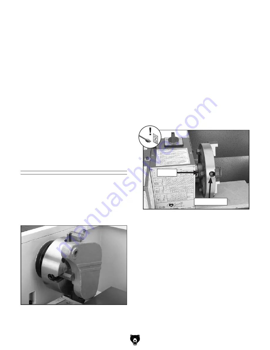
3. Loosen the hex nut on the back of the chuck
for each jaw (see
figure 21).
4. With assistance to support the workpiece,
use the chuck key to open each jaw until you
can position the workpiece flat against the
chuck face or evenly on the jaw steps.
figure 21. 4-jaw chuck components.
hex nut
scroll Keyway


