background image

g8690 variable speed Wood lathe

-2-

iNtrODuctiON

foreword

We are proud to offer the model g8690 variable 
speed Wood lathe. this machine is part of a grow-
ing grizzly family of fine woodworking machinery. 
When used according to the guidelines set forth in 
this manual, you can expect years of trouble-free, 
enjoyable  operation  and  proof  of  grizzly’s  com-
mitment to customer satisfaction.

the  specifications,  drawings,  and  photographs 
illustrated  in  this  manual  represent  the  model 
g8690 when the manual was prepared. however, 
owing  to  grizzly’s  policy  of  continuous  improve-
ment, changes may be made at any time with no 
obligation on the part of grizzly. For your conve-
nience, we always keep current grizzly manuals 
available  on  our  website  at 

www.grizzly.com

any  updates  to  your  machine  will  be  reflected 
in these manuals as soon as they are complete. 
visit our site often to check for the latest updates 
to this manual!

We stand behind our machines. if you have any 
service questions, parts requests or general ques-
tions about the machine, please call or write us at 
the location listed below.

grizzly industrial, inc.

1203 lycoming mall Circle

muncy, pa  17756

phone: (570) 546-9663

Fax: (800) 438-5901

e-mail: techsupport@grizzly.com

if you have any comments regarding this manual, 
please write to us at the address below:

grizzly industrial, inc.

C

/

technical documentation manager

p.o. Box 2069

Bellingham, Wa  98227-2069

email: manuals@grizzly.com

contact info

a  wood  lathe  is  used  to  turn  wood  stock.  the 
primary  components  of  the  wood  lathe  are  the 
headstock, the tailstock, and the tool rest. 

For  most  turning  procedures,  a  round  or  nearly- 
round  workpiece  is  clamped  between  the  head-
stock  spur  center  and  the  tailstock  live  center. 
the  tool  rest  is  positioned  to  provide  stability  to 
the chisel or other cutting tool while it is pressed 
into the workpiece. the lathe is turned 

ON

, which 

causes  the  spindle  to  rotate.  pressing  the  cut-
ting tool into the workpiece while it is turning cuts 
grooves  around  the  circumference  of  the  stock. 
moving  the  cutting  tool  along  the  length  of  the 
workpiece  allows  the  user  to  shape  the  work-
piece  into  perfect  cylinders,  tapers,  and  intricate 
designs.

another  option  is  faceplate  turning.  Faceplate 
turning  is  be  used  to  create  plates,  bowls,  and 
other shallow or open-faced forms. in this method, 
the tailstock is moved completely out of the way 
and the workpiece is attached to the faceplate on 
the headstock. again, the tool rest is positioned to 
provide support to the cutting tool.

once a rough shape is created on the lathe, it can 
be sanded smooth by moving the tool rest out of 
the way and carefully sanding along the length of 
the workpiece while the lathe is rotating.

to allow for greater versatility, the spindle speed 
can be adjusted by turning the speed adjustment 
knob on the control panel.

functional Overview

Summary of Contents for G8690

Page 1: ...athe OWNER S Manual Copyright 1999 By Grizzly Industrial Inc revised march 2008 JM Warning No portion of this manual may be reproduced in any shape or form without the written approval of Grizzly Industrial inc ds3299 printed in China ...

Page 2: ...AND THE USAGE OF PERSONAL PROTECTIVE EQUIPMENT 4HE MANUFACTURER WILL NOT BE HELD LIABLE FOR INJURY OR PROPERTY DAMAGE FROM NEGLIGENCE IMPROPER TRAINING MACHINE MODIFICATIONS OR MISUSE 3OME DUST CREATED BY POWER SANDING SAWING GRINDING DRILLING AND OTHER CONSTRUCTION ACTIVITIES CONTAINS CHEMICALS KNOWN TO THE 3TATE OF ALIFORNIA TO CAUSE CANCER BIRTH DEFECTS OR OTHER REPRODUCTIVE HARM 3OME EXAMPLES ...

Page 3: ...on 8 SECTION 3 SET UP 9 Set Up Safety 9 Items Needed for Set Up 9 Unpacking 9 Inventory 9 Clean Up 10 Site Considerations 10 Mounting 11 Assembly 12 Test Run 14 SECTION 4 OPERATIONS 15 Operation Safety 15 Spindle Turning 15 Speed Selector 16 Tool Rest 17 Faceplate Turning 17 Sanding Finishing 18 SECTION 5 ACCESSORIES 19 SECTION 6 MAINTENANCE 20 General 20 Lubrication 20 SECTION 7 SERVICE 21 Parts ...

Page 4: ...ndustrial Inc C O Technical Documentation Manager P O Box 2069 Bellingham WA 98227 2069 Email manuals grizzly com Contact Info A wood lathe is used to turn wood stock The primary components of the wood lathe are the headstock the tailstock and the tool rest For most turning procedures a round or nearly round workpiece is clamped between the head stock spur center and the tailstock live center The ...

Page 5: ...chine Weight 40 65 lbs Length Width Height 11 x 27 x 11 in Electrical Switch Push Button with Variable Speed Dial Switch Voltage 110V Cord Length 6 ft Cord Gauge 18 gauge Recommended Breaker Size 10 amp Plug Yes Motors Main Type TEFC Capacitor Start Induction Horsepower 1 3 HP Voltage 110V Prewired 110V Phase Single Amps 3 1A Speed 0 3025 RPM Cycle 60 Hz Number Of Speeds Variable Power Transfer Be...

Page 6: ...tock Taper MT 1 Tailstock Center Live Construction Bed Construction 1 26 Precision Steel Tubing Frame Construction Cast Iron Headstock Construction Cast Iron Tailstock Construction Cast Iron Paint Epoxy Other Related Information Bed Width 3 1 4 in Faceplate Size 4 in Other Specifications Country Of Origin China Warranty 1 Year Serial Number Location Top of Headstock Assembly Time 20 minutes Featur...

Page 7: ...FETY 2EAD NSTRUCTION ANUAL EFORE PERATING THIS ACHINE 4HE PURPOSE OF SAFETY SYMBOLS IS TO ATTRACT YOUR ATTENTION TO POSSIBLE HAZARDOUS CONDITIONS 4HIS MANUAL USES A SERIES OF SYMBOLS AND SIGNAL WORDS INTENDED TO CONVEY THE LEVEL OF IMPORTANCE OF THE SAFETY MESSAGES 4HE PROGRESSION OF SYMBOLS IS DESCRIBED BELOW 2EMEMBER THAT SAFETY MESSAGES BY THEMSELVES DO NOT ELIMINATE DANGER AND ARE NOT A SUBSTI...

Page 8: ...gjXi dch dg ajWg XVi c VcY X Vc c VXXZhhdg Zh 352 5 2 3 2 0 7 2 22 4 9 2 53 29 3AFETY NSTRUCTIONS FOR ACHINERY 2 6 534 93 72 3 BV Z V VW i d X ZX c dg Znh VcY VY_jhi c lgZcX Zh WZ dgZ ijgc c bVX cZgn 2 0 243 2 53 29 8 ZX dg W cY c dg b hVa cZY eVgih Wgd Zc eVgih addhZ Wdaih VcY Vcn di Zg XdcY i dch i Vi bVn beV g bVX cZ deZgVi dc GZeV g dg gZeaVXZ YVbV ZY eVgih WZ dgZ deZgVi dc 53 2 33 2 3 GZ Zg i...

Page 9: ...on t fly apart during operation 10 ADJUSTMENTS MAINTENANCE Make sure your wood lathe is turned OFF dis connected from its power source and all moving parts have come to a complete stop before starting any inspection adjustment or maintenance procedure 11 STOPPING LATHE DO NOT stop the lathe by using your hand against the workpiece Allow the lathe to stop on its own 12 AVOIDING ENTANGLEMENT Keep lo...

Page 10: ... ground prong from plug to fit into a two pronged outlet If the plug will not fit the outlet have the proper outlet installed by a qualified electrician Extension Cords We do not recommend using extension cords but if you find it absolutely necessary Use at least a 14 gauge cord that does not exceed 50 feet in length The extension cord must have a ground wire and plug pin A qualified electrician M...

Page 11: ...ase imme diately call Customer Service at 570 546 9663 for advice Save the containers and all packing materials for possible inspection by the carrier or its agent Otherwise filing a freight claim can be difficult When you are completely satisfied with the condi tion of your shipment inventory the contents Unpacking Inventory The following is a description of the main compo nents shipped with your...

Page 12: ...ance from your machine clean all moving parts or sliding contact surfaces Avoid chlorine based solvents such as acetone or brake parts cleaner that may damage painted surfaces Always follow the manufacturer s instruc tions when using any type of cleaning product Clean Up Gasoline and petroleum products have low flash points and can explode or cause fire if used to clean machinery DO NOT use these ...

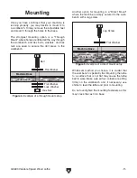
Page 13: ...i LVh Zg aVi LVh Zg AdX LVh Zg Zm Cji Figure 4 Example of a through mount setup ACHINE ASE 7ORKBENCH AV HXgZl aVi LVh Zg Figure 5 Example of a direct mount setup Another option for mounting is a Direct Mount where the machine is simply secured to the work bench with a lag screw Whichever method you choose it is crucial that the workbench is perfectly flat Mounting the lathe to a surface that is no...

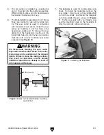
Page 14: ...lstock The handle located under the lathe bed can be loosened allowing the tailstock to slide up and down the length of the guide rails or the hand wheel can be loosened allowing the threaded spindle to move back and forth in the tailstock for fine adjustment See Figure 9 Figure 8 Tool rest mounted in bracket 3 The tool rest fits into the tool rack shaft and is tightened in place with a setscrew M...

Page 15: ...he spur center is ejected See Figure 10 Hex Nut Spur Center Motor Housing MT 1 Figure 10 Hex nut installed before inserting spur center We recommend cleaning the spur center taper with mineral spirits Refer to the safe ty warnings on the container of the mineral spirits Failure to clean the mating surfaces may result in separation and an unsafe condition Separation is usually a result of oil or gr...

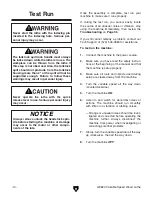
Page 16: ...little or no vibration or rubbing noises Strange or unusual noises should be inves tigated and corrected before operating the machine further Always disconnect the machine from power when investigating or correcting potential problems 7 Slowly turn the variable speed dial all the way up clockwise then all the way down 8 Turn the machine OFF Never start the lathe with the indexing pin inserted in t...

Page 17: ...t caught in machinery and cause seri ous personal injury Keep loose clothing and long hair away from moving machinery NOTICE If you have never used this type of machine or equipment before We strongly rec ommend that you read books trade maga zines or get formal training before begin ning any projects Regardless of the con tent in this section Grizzly Industrial will not be held liable for acciden...

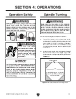
Page 18: ...before tapping the spur center in 5 While supporting the workpiece slide the tail stock close to the end of the workpiece and lock it into place 6 Line up the live center with the workpiece center Turn the handwheel to press the point of the live center into the workpiece 7 Lock the tailstock in place 1 4 Figure 13 Spur center set into wood stock 3 Hold the spindle vertically and support it on a s...

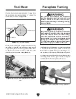
Page 19: ...to the headstock spindle This type of turning is usu ally done with open faced workpieces like bowls If screws cannot be placed in the workpiece then a backing block can be glued to the workpiece and attached to the faceplate with screws Figure 17 Typical faceplate turning operation Faceplate Turning The contact area between the workpiece and the faceplate must be flush with one another Failure to...

Page 20: ...iece of scrap wood that is flat on both sides DD9 769 Figure 18 Correct and incorrect screw types for mounting faceplate to workpiece After turning the workpiece can be sanded as shown in Figure 20 and finished in the same manner before removing it from the lathe Sanding Finishing Figure 20 Typical sanding operation Whenever sanding or finishing move the tool rest holder out of the way to increase...

Page 21: ...ol Table Plus Figure 24 Model H6542 Robert Sorby 8 PC Set H6542 Robert Sorby HSS 8 PC Turning Set H3102 H3103 H3104 Gouge Slipstones H1064 6 PC Deluxe HSS Lathe Chisel Set G9863 8 PC HSS Lathe Chisel Set H0507 20 Swan Neck Hollowing Tool H0508 24 Swan Neck Hollowing Tool Figure 21 Model H9586 Lathe Fundamentals guide book H9586 Lathe Fundamentals With more than 300 color photos this fourth authori...

Page 22: ...st and pitting Wiping the lathe clean after every use ensures that wood dust isn t allowed to trap moisture against bare metal surfaces Some woodworkers recommend using automo tive paste wax on exposed steel and cast iron surfaces The wax provides a layer of protection Avoid waxes that contain silicone or other synthet ic ingredients These materials can find their way into lumber that s being work...

Page 23: ...G8690 Variable Speed Wood Lathe 21 SECTION 7 SERVICE Parts Breakdown ...

Page 24: ...AP SCREW M3 5 X 8 21 P80028 BALL BEARING 80028 65 P8690065 ELECTRONIC CIRCUIT 22 P8690022 TAPER SHAFT 66 P8690066 SPEED KNOB 23 P8690023 TAILSTOCK 67 P8690067 SPECIAL NUT M8 1 25 X 4 24 P8690024 TAPER CASE 68 P8690068 POTENTIAL DEVICE 25 P8690025 GUIDE SCREW M8 1 25 X 70 69 PS08M PHLP HD SCR M5 8 X 12 26 P9247062 COLLAR 70 P8690070 TOP PLATE 27 P8690027 HAND WHEEL 71 G8992 POWER SWITCH 28 PSS03M S...

Page 25: ...TT TTTT TTTT TTTT TTTT L Vi h ndjg V Z gdje4 TTTT TTTT TTTT TTTT TTTT TTTT dl adc VkZ ndj WZZc V lddYldg Zg bZiValdg Zg4 TTTT NZVgh TTTT NZVgh TTTT NZVgh TTTT NZVgh dl bVcn d ndjg bVX cZh dg iddah VgZ g ooan4 TTTT TTTT TTTT TTTT 9d ndj i c ndjg bVX cZ gZegZhZcih V ddY kVajZ4 TTTTTNZh TTTTTCd LdjaY ndj gZXdbbZcY g ooan cYjhig Va id V g ZcY4 TTTTTNZh TTTTTCd LdjaY ndj Vaadl jh id jhZ ndjg cVbZ Vh V ...

Page 26: ...INDUSTRIAL inc p o box 2069 bellingham wa 98227 2069 Place Stamp Here tape along edges please do not staple Name_______________________________ Street_______________________________ City______________State______Zip______ Send a Grizzly Catalog to a friend ...

Page 27: ...the State of Washington County of Whatcom We shall in no event be liable for death injuries to persons or property or for incidental contingent special or consequential damages arising from the use of our products To take advantage of this warranty contact us by mail or phone and give us all the details We will then issue you a Return Number which must be clearly posted on the outside as well as t...

Page 28: ...IRECT AND 3AVE WITH RIZZLY n 4RUSTED 0ROVEN AND A REAT 6ALUE 2 s 3 52 2 2 s 2 23 3 00 7 4 523 s 2 30 3 7 4 52 6ISIT UR 7EBSITE 4ODAY ND ISCOVER 7HY RIZZLY S 4HE NDUSTRY EADER ALL 4ODAY OR 2 ULL OLOR ATALOG ...

Reviews: