background image

G8694/G8695/G8889 Air Compressors

-3-

9.

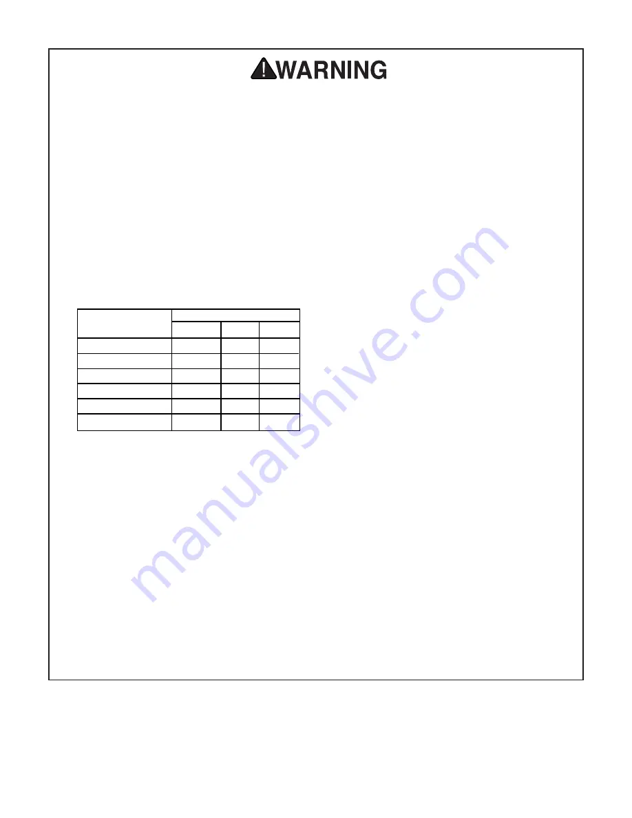
USE PROPER EXTENSION CORD

. Make

sure your extension cord is in good condi-
tion. Conductor size should be in accor-
dance with the chart below. The amperage
rating should be listed on the motor or tool
nameplate. An undersized cord will cause a
drop in line voltage resulting in loss of
power and overheating. Your extension
cord must also contain a ground wire and
plug pin. Always repair or replace exten-
sion cords if they become damaged. 

Minimum Gauge for Extension Cords

10. WEAR PROPER APPAREL.

Do not wear

loose clothing, gloves, neckties, rings,
bracelets, or other jewelry which may get
caught in moving parts. Non-slip footwear
is recommended. Wear protective hair cov-
ering to contain long hair.

11. ALWAYS USE SAFETY GLASSES.

Also

use face or dust mask if cutting operation is
dusty. Everyday eyeglasses only have
impact resistant lenses, they are NOT safe-
ty glasses.

12. SECURE WORK.

Use clamps or a vise to

hold work when practical. It’s safer than
using your hand and frees both hands to
operate tool.

LENGTH

AMP RATING

25ft

50ft

100ft

0-6

18

16

16

7-10

18

16

14

11-12

16

14

12

13-16

14

12

12

17-20

12

12

8

21-30

10

10

No

Safety Instructions For Power Tools

13. DON’T OVERREACH.

Keep proper foot-

ing and balance at all times.

14. MAINTAIN TOOLS WITH CARE.

Keep

tools sharp and clean for best and safest
performance. Follow instructions for lubri-
cating and changing accessories.

15. DISCONNECT TOOLS

before servicing

and changing accessories, such as blades,
bits, cutters, and the like.

16. REDUCE THE RISK OF UNINTENTION-

AL STARTING.

Make sure switch is in off

position before plugging in.

17. USE RECOMMENDED ACCESSORIES.

Consult the owner’s manual for recom-
mended accessories. The use of improper
accessories may cause risk of injury.

18. CHECK DAMAGED PARTS.

Before fur-

ther use of the tool, a guard or other part
that is damaged should be carefully
checked to determine that it will operate
properly and perform its intended function.
Check for alignment of moving parts, bind-
ing of moving parts, breakage of parts,
mounting, and any other conditions that
may affect its operation. A guard or other
part that is damaged should be properly
repaired or replaced.

19. NEVER LEAVE TOOL RUNNING UNAT-

TENDED. TURN POWER OFF.

Don’t

leave tool until it comes to a complete stop.

Summary of Contents for G8694

Page 1: ...NSTRUCTION MANUAL COPYRIGHT 1999 BY GRIZZLY INDUSTRIAL INC 1821 VALENCIA ST BELLINGHAM WA 98226 WARNING NO PORTION OF THIS MANUAL MAY BE REPRODUCED IN ANY SHAPE OR FORM WITHOUT THE WRITTEN APPROVAL OF GRIZZLY INDUSTRIAL INC NOVEMBER 1999 PRINTED IN CHINA G8694 G8695 G8889 ...

Page 2: ... 5 GROUNDING 5 EXTENSION CORDS 5 SETTING UP AND OPERATING COMMENTARY 6 UNPACKING 7 SITE CONSIDERATIONS 7 PREPARING FOR USE 8 STARTING 9 PRESSURE REGULATOR 9 CONNECTING TOOLS 10 AIR CONTROL VALVE 10 MAINTENANCE EACH USE 11 AFTER FIRST 50 HOURS 12 WEEKLY 12 EVERY 300 HOURS 12 TROUBLESHOOTING 13 PARTS BREAKDOWN AND PARTS LISTS 14 15 WARRANTY AND RETURNS 16 ...

Page 3: ...mable or noxious fumes may exist Keep work area well lighted For Your Own Safety Read Instruction Manual Before Operating This Equipment Indicates an imminently hazardous situation which if not avoided WILL result in death or serious injury Indicates a potentially hazardous situation which if not avoided COULD result in death or serious injury Indicates a potentially hazardous situation which if n...

Page 4: ... AMP RATING 25ft 50ft 100ft 0 6 18 16 16 7 10 18 16 14 11 12 16 14 12 13 16 14 12 12 17 20 12 12 8 21 30 10 10 No Safety Instructions For Power Tools 13 DON T OVERREACH Keep proper foot ing and balance at all times 14 MAINTAIN TOOLS WITH CARE Keep tools sharp and clean for best and safest performance Follow instructions for lubri cating and changing accessories 15 DISCONNECT TOOLS before servicing...

Page 5: ... This is preset to 150 PSI Operating this equipment has the potential to propel debris into the air which can cause eye injury Always wear safety glass es or goggles when operating equipment Everyday glasses or reading glasses only have impact resistant lenses they are not safety glasses Be certain the safety glass es you wear meet the appropriate stan dards of the American National Standards Inst...

Page 6: ...us injury may occur In the event of an electrical short grounding reduces the risk of electric shock by providing a path of least resistance to disperse electric cur rent These machines are equipped with power cords having an equipment grounding conductor See Figure 1 The outlet must be properly installed and grounded in accordance with all local codes and ordinances These air compressors are wire...

Page 7: ...ess below Grizzly Industrial Inc C O Technical Documentation P O Box 2069 Bellingham WA 98227 2069 Most importantly we stand behind our machines If you have any service questions or parts requests please call or write us at the location listed below Grizzly Industrial Inc 1203 Lycoming Mall Circle Muncy PA 17756 Phone 570 546 9663 Fax 800 438 5901 E Mail techsupport grizzly com Web Site http www g...

Page 8: ...ion 2 Circuit Requirements for the needs for your particular compressor Also make sure the compressor is not operating in an environment where there are any explosive flammable or caustic fumes or gases A clear and well ventilated area is best for its safe operation Place the compressor on a solid and level sur face Make sure that the hoses you attach to sup ply your pneumatic device will be unres...

Page 9: ...ve impact resistant lenses they are not safety glasses Be certain the safety glass es you wear meet the appropriate stan dards of the American National Standards Institute ANSI Operating this equipment has the potential for hearing damage to occur especially if operated for a long period of time Use ANSI American National Standards Institute approved ear muff or ear plugs when using this equipment...

Page 10: ... button on top of the control box should be in the fully depressed position see Figure 3 before connecting to the power supply Close the drain cock on the tank Pull the switch to the ON position Starting Fig 3 Start switch and gauges Check the pressure gauge to see that the tank pressure gets up to approximately 110 115 PSI On Off Switch Output Gauge Figure 4 Pressure regulator Always wear safety ...

Page 11: ...ools to be powered Air tools being operated with insufficient air volume will not perform their func tion satisfactorily Connect the tool using a good quality air line with an adequate length to reach from the compressor to the point of use Quick connect couplers are a good option for fast and sure connection of tools and air hoses Make certain the air hose will not be placed in a position where i...

Page 12: ...ding upon the amount of use and the weather conditions a certain amount of condensed water may be released For longevity of the compres sor seals and the air tools you connect it is best to keep the tanks free of water The tanks are best drained if the drain cocks are opened when the system is pressurized Once water has stopped coming out you can close the drain cocks Each Use Fig 6 Typical locati...

Page 13: ...essors Weekly Every 300 Hours If the compressor is used on a regular daily basis perform the following checks each week 1 Rinse the air filter foam element in water 2 Check for loose bolts or fittings After every 300 hours or 3 months of regular operation perform the following maintenance items 1 Change compressor motor oil 2 Rinse the air filter foam element in water 3 Check for air leaks and cor...

Page 14: ...ns 3 Motor will not start if tank pressure is too high 4 Thermal overload switch has tripped wait for motor to cool then reset switch by pressing red button 1 Inspect cord or plug for damaged insulation and shorted wires 2 Inspect all connections on motor for loose or shorted terminals or worn insulation 3 Install correct fuses or circuit breakers 1 Check air hoses and all connections for leaks 2 ...

Page 15: ...r 035 P8694035 Valve Gasket 036 P8694036 Valve Plate 037 P8694037 Check Valve 038 P8694038 Valve Inner Gasket 039 P8694039 Valve Plate 040 P8694040 Cylinder Head Gasket 041 P8694041 Cylinder Head 042 P8694042 Right Angle Connector 043 P8694043 Hex Bolt M6 x 50 044 P8694044 Air Filter 045 P8694045 Washer 4 mm 046 P8694046 Wing Nut M4 047 P8694047 Nut M6 048 P8694048 Capacitor 049 P8694049 Fan Cover...

Page 16: ...G8694 G8695 G8889 Air Compressors 15 ...

Page 17: ...shall be tried in the State of Washington County of Whatcom We shall in no event be liable for death injuries to persons or property or for incidental contingent spe cial or consequential damages arising from the use of our products To take advantage of this warranty contact us by mail or phone and give us all the details We will then issue you a Return Number which must be clearly posted on the o...

Reviews: