


g8749 drum/Flap sander
-11-
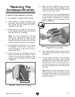
Mounting
due to the significant forces exerted on the
sander during operation, you must mount it to a
workbench. We recommend that you use one of
the following methods to secure your sander to
the workbench before using it.
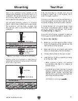
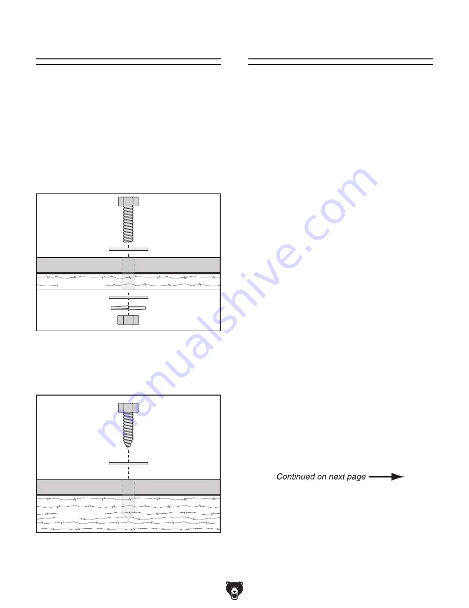
the strongest mounting option is a "through
Mount" where holes are drilled all the way through
the workbench, and hex bolts, washers, and
hex nuts are used to secure the sander to the
workbench.
-ACHINE"ASE
7ORKBENCH
AV\HXgZl
;aViLVh]Zg
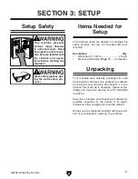
Figure 8. Example of a direct mount setup.
another option for mounting is a "direct Mount"
where the machine is simply secured to the work-
bench with a lag screw.
-ACHINE"ASE
7ORKBENCH
7dai
;aViLVh]Zg
;aViLVh]Zg
AdX`LVh]Zg
=ZmCji
Figure 7. Example of a through mount setup.
test Run
once the assembly is complete, test run your
machine to make sure it runs properly and is
ready for regular operation.
the test run consists of verifying the following: 1)
the motor powers up and runs correctly, and 2)
the safety disabling mechanism works correctly.
if, during the test run, you cannot easily locate
the source of an unusual noise or vibration, stop
using the machine immediately, then review
troubleshooting on Page 20.
if you still cannot remedy a problem, contact our
tech support at (570) 546-9663 for assistance.
to test run the machine:
1. Make sure you have read the safety instruc-
tions at the beginning of the manual and that
the machine is set up properly.
2. Make sure all tools and objects used during
setup are cleared away from the machine.
3. Connect the machine to the power source.
4. Verify that the machine is operating correctly
by turning the it
ON
.
—When operating correctly, the machine
runs smoothly with little or no vibration or
rubbing noises.
— investigate and correct strange or unusual
noises or vibrations before operating the
machine further. always disconnect the
machine from power when investigating or
correcting potential problems.


