background image

g8749 drum/Flap sander

-19-

Replacing Flap 

Sandpaper/brushes

to replace the flap sandpaper or brushes:

1.  disConnECt sandEr FroM poWEr!

2.  While  holding  the  outside  end  plate  of  the 

flap sander, remove the arbor bolt and flange, 
then  remove  the  flap  sander  and  place  it 
upright on a flat surface.

3.  remove the top end plate, then remove one 

or two brushes to gain access to the retaining 
bars that secure the sandpaper.


Note: 

All  of  the  replacement  sandpaper 

needs  to  be  oriented  and  installed  so  that 
the  abrasive  side  faces  the  same  direction 
and will face forward and down when the flap 
sander is properly mounted on the machine.

4.  Each retaining bar holds two 4 

1

2

" x 6" pieces 

of sandpaper. loosen the two screws secur-
ing the retaining bar, then pull the old sand-
paper pieces away.

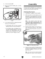
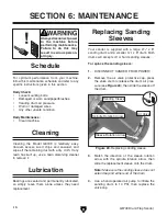
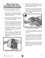
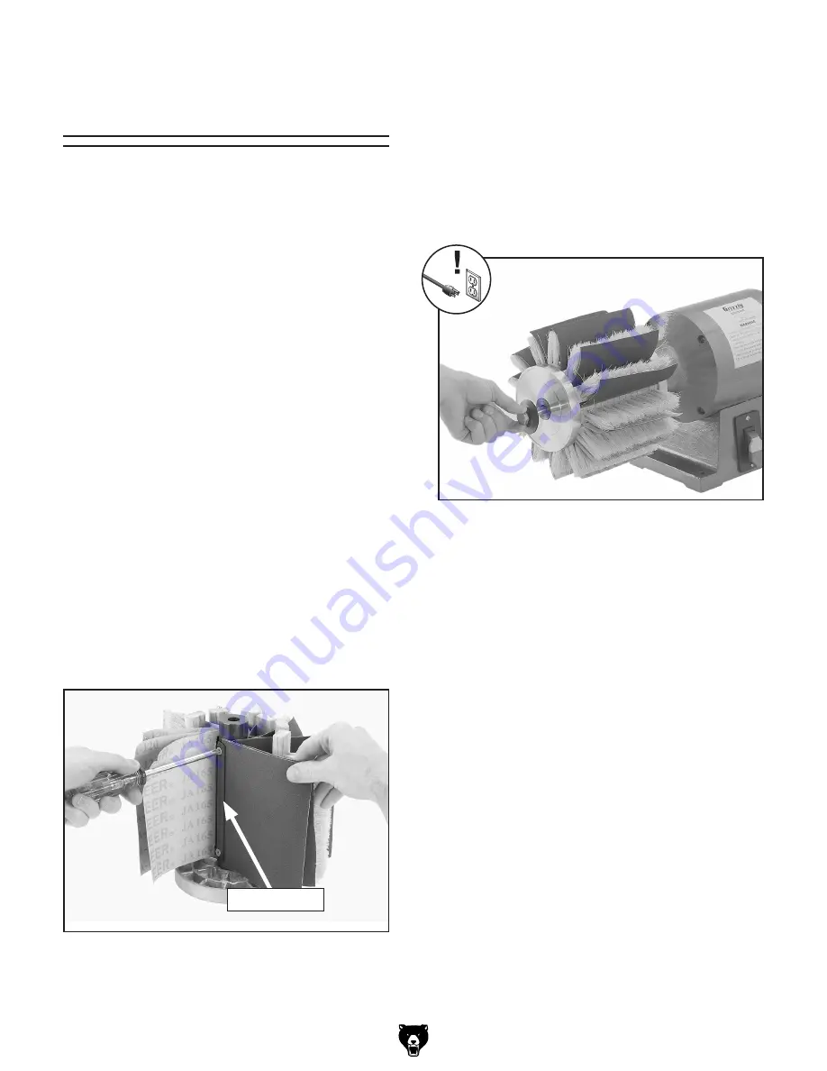
5.  Cut  two  new  pieces  of  sandpaper  from  the 

selected grit, then slip them under the retain-
ing bar so that the abrasive side faces away 
from the center of the flap sander, as shown 
in 

Figure 21.

6.  Make  sure  the  sandpaper  pieces  are  even 

with  one  another  and  are  centered  in  the 
retaining bar, then re-tighten the retaining bar 
screws to hold them in place.

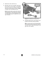
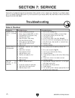
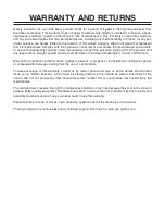
7.  if a flap brush is worn out or damaged, replace 

it with a new one. insert each brush into the 
lower end plate and between two sandpaper 
pieces attached to the same retaining bar, as 
shown in 

Figure 22.

Figure 21. replacing flap sandpaper.

retaining Bar

8.  after replacing the sandpaper and positioning 

the brushes, place the top end plate onto the 
flap sander.

9.  as  you  lightly  push  down  on  the  top  plate, 

correctly position one brush to align with the 
recessed slot in the top plate, then rotate the 
flap  sander  and  work  on  the  one  next  to  it. 
Continue this process until all of the brushes 
are correctly aligned and fully seated into the 
top plate.


Note: 

When storing the flap sander in a dry, 

protected  place,  secure  the  bottom  and  top 
end plates with tie wraps or string so that the 
end plates do not come loose and allow the 
brushes to fall out.

Figure 22. sandpaper and brushes properly 

configured on the flap sander.

Summary of Contents for G8749

Page 1: ...NER S Manual Copyright 2000 By Grizzly Industrial Inc REVISED NOVEMBER 2008 TS Warning No portion of this manual may be reproduced in any shape Or form without the written approval of Grizzly Industri...

Page 2: ...ERSONAL PROTECTIVE EQUIPMENT 4HE MANUFACTURER WILL NOT BE HELD LIABLE FOR INJURY OR PROPERTY DAMAGE FROM NEGLIGENCE IMPROPER TRAINING MACHINE MODIFICATIONS OR MISUSE 3OME DUST CREATED BY POWER SANDING...

Page 3: ...ory 10 Site Considerations 10 Test Run 11 Mounting 12 Assembly 12 SECTION 4 OPERATIONS 15 Operation Safety 15 Sanding Tips 15 ON OFF Switch 16 Drum Sanding 16 Flap Sanding 16 SECTION 5 ACCESSORIES 17...

Page 4: ...d photographs of the machine we used when writ ing this manual However sometimes errors do happen and we apologize for them Also owing to our policy of continuous improve ment your machine may not exa...

Page 5: ...G8749 Drum Flap Sander 3 Identification Figure 3 Model G8749 identification Mounting Holes Motor Sanding Drum ON OFF Switch Flap Sander...

Page 6: ...ZY C B6 Motor IneZ I 8 8VeVX idg HiVgi cYjXi dc dghZedlZg E KdaiV Z K E VhZ H c aZ 6beh 6 HeZZY GEB 8nXaZ o CjbWZg D HeZZYh EdlZg IgVch Zg 9 gZXi 9g kZ 7ZVg c h H ZaYZY VcY EZgbVcZcian HZVaZY Other Sp...

Page 7: ...EAD NSTRUCTION ANUAL EFORE PERATING THIS ACHINE 4HE PURPOSE OF SAFETY SYMBOLS IS TO ATTRACT YOUR ATTENTION TO POSSIBLE HAZARDOUS CONDITIONS 4HIS MANUAL USES A SERIES OF SYMBOLS AND SIGNAL WORDS INTEND...

Page 8: ...dch dg ajWg XVi c VcY X Vc c VXXZhhdg Zh 352 5 2 3 2 0 7 2 22 4 9 2 53 29 3AFETY NSTRUCTIONS FOR ACHINERY 2 6 534 93 72 3 BV Z V VW i d X ZX c dg Znh VcY VY_jhi c lgZcX Zh WZ dgZ ijgc c bVX cZgn 2 0 2...

Page 9: ...conditions Use this and other machinery with caution and respect Failure to do so could result in serious per sonal injury damage to equipment or poor work results Like all machinery there is potentia...

Page 10: ...e that it is grounded DO NOT remove ground prong from plug to fit into a two pronged outlet If the plug will not fit the outlet have the proper outlet installed by a qualified electrician Extension Co...

Page 11: ...scription Qty Wrenches 14 19mm 1 Each Mounting Hardware Page 11 As Needed Items Needed for Setup Your machine was carefully packaged for safe transportation Remove the packaging materials from around...

Page 12: ...ned at your local hardware store SUFFOCATION HAZARD Immediately discard all plas tic bags and packing materi als to eliminate choking suf focation hazards for children and animals Workbench Load Refer...

Page 13: ...gular operation The test run consists of verifying the following 1 The motor powers up and runs correctly and 2 the safety disabling mechanism works correctly If during the test run you cannot easily...

Page 14: ...ide Attaching Flap Sander 1 DISCONNECT SANDER FROM POWER 2 When removed from the shipping box the flap sander is held together by two tie wraps Hold the assembly together from top to bot tom then remo...

Page 15: ...n arrows and the rota tion arrow on the spindle housing match Alwayscheckthesanding drum air pressure before using it Only use a hand operated air pump to inflate the sanding drum to 10 PSI If the dru...

Page 16: ...e uses the arbor bolt with left hand threads which tightens by rotating it counterclockwise The right spindle arbor bolt has right hand threads and tightens by rotat ing it clockwise Figure 13 Install...

Page 17: ...er is a safe tool when used properly In addition to the safety instructions in this manual the most important safety consideration is to use common sense at all times Follow these rules when sanding M...

Page 18: ...le when the sanded edge is to be sharp Make sure the sanding sleeve is mounted on the drum and sander so that the sleeve rotation and spindle rotation match The spindle will always rotate toward the o...

Page 19: ...irator can greatly reduce your risk Compatible with safety glasses Aluminum Oxide Sanding Sleeves G9196 31 4 Diameter 60 Grit G9197 31 4 Diameter 80 Grit G9198 31 4 Diameter 100 Grit G9199 31 4 Diamet...

Page 20: ...ning Lubrication Bearings are sealed and permanently lubricated so simply leave them alone unless they need replacement Replacing Sanding Sleeves Your sander is supplied with a large 43 4 x 8 sanding...

Page 21: ...center of the flap sander as shown in Figure 21 6 Make sure the sandpaper pieces are even with one another and are centered in the retaining bar then re tighten the retaining bar screws to hold them i...

Page 22: ...ct motor wiring connections Page 23 6 Ensure circuit size is correct replace weak breaker 7 Check fix broken disconnected or corroded wires 8 Replace switch 9 Test repair replace Machine stalls or is...

Page 23: ...kpiece against the sanding abrasive 2 Use different stock or accept the characteristics of the stock and plan on cleaning replacing sandpaper frequently Burn marks on workpiece 1 Sandpaper grit too fi...

Page 24: ...isconnected or connected during any wiring task to ensure tight connections 4 MOTOR WIRING The motor wiring shown in these diagrams is current at the time of printing but it may not match your machine...

Page 25: ...AFETY ON PAGE 22 HiVgi 8VeVX idg B 9 K68 gdjcY Motor ON OFF Switch 110VAC NEMA 5 15 Plug As Recommended WARNING SHOCK HAZARD Disconnect power before working on wiring CZjigVa gdjcY di Wiring Diagram F...

Page 26: ...24 G8749 Drum Flap Sander 6 Parts Breakdown SECTION 9 PARTS...

Page 27: ...29 STRAIN RELIEF 11 G9211 SANDING SLEEVE 4 3 4 X 8 120G 30 PWRCRD100L POWER CORD 110V W 5 15 PLUG 12 P8749012 AIR VALVE 31 P8749031 BASE 13 P8749013 VALVE CAP 32 P8749032 S CAPACITOR 400M 125V 3 X 1 3...

Page 28: ...26 G8749 Drum Flap Sander...

Page 29: ...TT TTTT TTTT TTTT TTTT L Vi h ndjg V Z gdje4 TTTT TTTT TTTT TTTT TTTT TTTT dl adc VkZ ndj WZZc V lddYldg Zg bZiValdg Zg4 TTTT NZVgh TTTT NZVgh TTTT NZVgh TTTT NZVgh dl bVcn d ndjg bVX cZh dg iddah VgZ...

Page 30: ...I HI6EA DA9 6ADC 9DII 9 A C DA9 6ADC 9DII 9 A C 2 9 5342 0 8 7 EaVXZ HiVbe ZgZ CVbZTTTTTTTTTTTTTTTTTTTTTTTTTTTTTTT HigZZiTTTTTTTTTTTTTTTTTTTTTTTTTTTTTTT 8 inTTTTTTTTTTTTTTHiViZTTTTTTO eTTTTTT HZcY V g...

Page 31: ...h Vaa WZ ig ZY c i Z HiViZ d LVh c idc 8djcin d L ViXdb LZ h Vaa c cd ZkZci WZ a VWaZ dg YZVi c_jg Zh id eZghdch dg egdeZgin dg dg cX YZciVa Xdci c Zci heZX Va dg XdchZfjZci Va YVbV Zh Vg h c gdb i Z...

Page 32: ...RECT AND 3AVE WITH RIZZLY n 4RUSTED 0ROVEN AND A REAT 6ALUE 2 s 3 52 2 2 s 2 23 3 00 7 4 523 s 2 30 3 7 4 52 6ISIT UR 7EBSITE 4ODAY ND ISCOVER 7HY RIZZLY S 4HE NDUSTRY EADER ALL 4ODAY OR 2 ULL OLOR AT...

Reviews: