background image

Model G9743 (Mfg. since 12/07)

-35-

READ ELECTRICAL SAFETY 

ON PAGE 33!

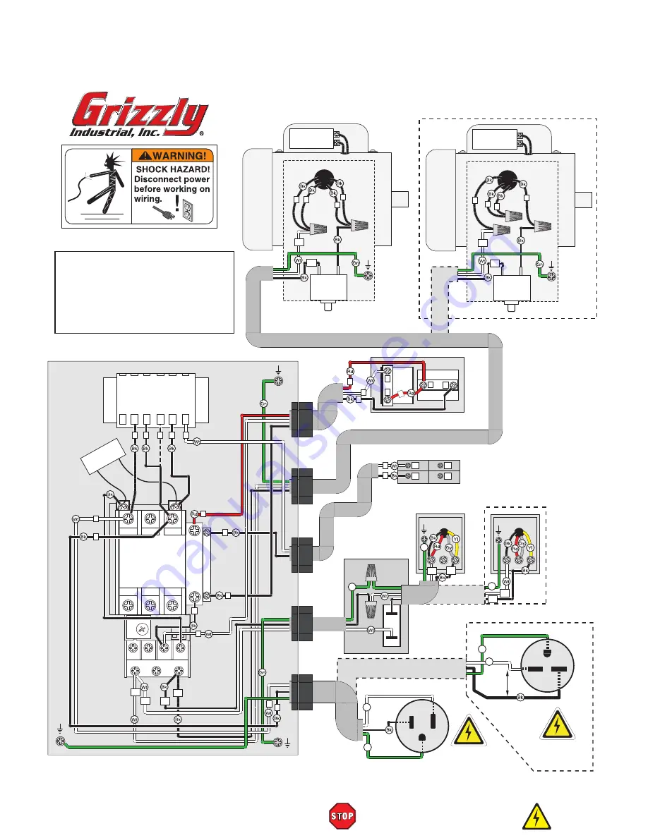
Wiring Diagram

1

Hot

Hot

Ground

220

VAC

220 VAC

Start Capacitor

150MFD

250VAC

3

2

4

1

Pump

ON/OFF

Switch

Headstock Switch

Transformer

Contactor

TECO

CU-18

Thermal
Overload

FN-1748-14

97NO 98NO

2T1

6T3

4T2

95NC 96NC

2T1

6T3

4T2

1L1

0V 110V 220V

5L3

3L2

Ground

U1

Ground

U1

V1

Start Capacitor

150MFD

250VAC

1

3

4

2

Ground

U1

V1

V1

U2

V2

Ground

1

4

4

3

3

4

1UF

120 Ohm

0

7

L

N

N

N

L

L

Ground

Optional 

220V Connection

(Prewired) 

110V Connection

MOTOR

MOTOR

Main Electrical Box

110 VAC

5-15 Plug 

Optional

220V Connection

3

4

2

3

2

2

Overload

Breaker

20A

Overload

Breaker

20A

Main ON/OFF Switch

OFF Switch

ON

Switch

Optional 

220V

Connection

110V

Connection

12

11

23

24

0

1

Pump

Pump

6-15 Plug 

G

Wt

Gn

Hot

Neutral

Gn

Wt

Gn

Gn

Gn

Ground

U2

V2

U2

V2

Fuse 2A

22

24

26

28

30

L

220V CONVERSION 

1.  Disconnect power.
2.  Rewire main motor.
3.  Rewire pump.
4.  Rewire transformer (move L wire from 110V
     terminal to 220V terminal).
5.  Install 220V 6-15 plug.


Summary of Contents for G9743

Page 1: ...UAL COPYRIGHT MARCH 2006 BY GRIZZLY INDUSTRIAL INC REVISED MAY 2009 CR WARNING NO PORTION OF THIS MANUAL MAY BE REPRODUCED IN ANY SHAPE OR FORM WITHOUT THE WRITTEN APPROVAL OF GRIZZLY INDUSTRIAL INC F...

Page 2: ...g grinding tool integrity and the usage of personal protective equipment The manufacturer will not be held liable for injury or property damage from negligence improper training machine modifications...

Page 3: ...Chart 13 Clean Up 14 Site Considerations 14 Shipping Bracket 15 Work Stop 15 Handle 16 Wheels and Feet 16 Test Run 17 Recommended Adjustments 17 SECTION 4 OPERATIONS 18 Operation Safety 18 Vise 18 Bl...

Page 4: ...fety Instructions 32 Electrical Components 33 Electrical Components 34 Wiring Diagram 35 SECTION 9 PARTS 36 Base Stand 36 Headstock 37 Misc Assemblies 38 Gearbox 39 Electrical Box 40 Parts List 41 Not...

Page 5: ...However owing to Grizzly s policy of con tinuous improvement changes may be made at any time with no obligation on the part of Grizzly For your convenience we always keep current Grizzly manuals avail...

Page 6: ...ht 464 lbs Length x Width x Height 26 x 57 x 46 in Must Ship Upright Yes Electrical Power Requirement 110V or 220V Single Phase 60 Hz Prewired Voltage 110V Full Load Current Rating 18 6A at 110V 9 3A...

Page 7: ...ngular Width at 30 Deg 10 in Max Capacity Round at 30 Deg 10 in Max Capacity Rectangular Height at 45 Deg 4 in Max Capacity Rectangular Width at 45 Deg 8 in Max Capacity Round at 45 Deg 6 in Construct...

Page 8: ...e D Blade E ON OFF Switch F 11 2 HP Motor G Speed Control Knob H Feed Rate ON OFF Valve I Workstop Figure 1 Main view of machine features A B F E D C J Wheels K Bandsaw Stand L Pump Toggle Switch M Li...

Page 9: ...PRODUCES DUST For Your Own Safety Read Instruction Manual Before Operating this Machine The purpose of safety symbols is to attract your attention to possible hazardous conditions This manual uses a s...

Page 10: ...g and changing accessories 16 MAKE SURE GUARDS ARE IN PLACE AND WORK CORRECTLY BEFORE USING MACHINERY Safety Instructions for Machinery 17 REMOVE ADJUSTING KEYS AND WRENCHES Make a habit of checking f...

Page 11: ...de Inspect blades for cracks and missing teeth before each use 2 HAND PLACEMENT Never position fin gers or thumbs in line with the cut Hands could be crushed in vise or from falling machine components...

Page 12: ...ion Device The Model G9743 comes prewired with a NEMA 5 15 plug for connection to power If you rewire the motor to 220V we recommend using the plug and receptacle shown in Figure 2 for 220V Extension...

Page 13: ...d inventory the contents Wear safety glasses dur ing the entire set up pro cess This machine presents serious injury hazards to untrained users Read through this entire manu al to become familiar with...

Page 14: ...ems Box Contents Figure 3 Qty Metal Cutting Bandsaw not shown 1 A Handle 1 B Feet 2 C Wheel 2 D Work Stop 1 E Work Stop Leaf Bolt 1 E Work Stop Rod 1 G Axle 1 H Hardware Bag Qty Flat Washer 5 8 Wheels...

Page 15: ...Model G9743 Mfg since 12 07 13 5mm Hardware Recognition Chart...

Page 16: ...o protect them from corrosion during ship ment Remove this protective coating with a sol vent cleaner or citrus based degreaser such as Grizzly s G7895 Degreaser To clean thoroughly some parts may nee...

Page 17: ...hex nut and remove the shipping bracket shown in Figure 5 Shipping Bracket Figure 5 Removing shipping bracket Shipping Bracket Work Stop Components and Hardware Needed Qty Work Stop 1 Work Stop Rod 1...

Page 18: ...le Position the handle onto the end of the cabinet as shown and fasten it in place with the four hex bolts eight flat washers and four hex nuts Figure 8 Foot Locations Handle Figure 9 Installing wheel...

Page 19: ...nts to ensure accurate cutting results Step by stepinstructionsonverifyingtheseadjust ments can be found in SECTION 7 SERVICE ADJUSTMENTS Factory adjustments that should be verified 1 Blade Tracking P...

Page 20: ...caused by lack of training The vise on the Model G9743 has a positive lock ing feature that improves productivity by open ing the vise jaws just enough to slide material through To use the positive lo...

Page 21: ...AND ALLOW IT TO COME TO A COMPLETE STOP 2 Determine the best speed for your cut The table in Figure 15 is provided as a rough guideline Material thickness type of blade used and if cutting fluid is us...

Page 22: ...on Page 25 Cutting Fluid System FIRE HAZARD DO NOT cut magnesium when using oil water solutions as a cutting fluid Always use a cutting fluid intend ed for magnesium The water in the solution will ca...

Page 23: ...acturer for unanswered questions Use the selections below to choose the appro priate cutting fluids For cutting low alloy low carbon and gen eral purpose category metals with a bi metal blade use a wa...

Page 24: ...the spring tension will reduce the feed pressure Figure 21 Reading chip characteristics Chips are silvery thin small or powdery Increase feed rate Chips are large curled blue or brown or smoking Decre...

Page 25: ...ever start a cut with the blade in contact with the workpiece see Figure 22 Chips should be curled and silvery If the chips are thin and powder like increase your feed rate Burned chips indicate a nee...

Page 26: ...aker H2308 104 1 2 x 1 x 032 14 TPI Raker H2315 104 1 2 x 1 x 032 3 4 Variable Pitch H2316 104 1 2 x 1 x 032 4 6 Variable Pitch H2317 104 1 2 x 1 x 032 5 8 Variable Pitch H2318 104 1 2 x 1 x 032 6 10...

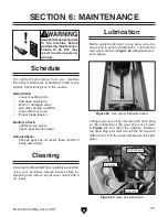
Page 27: ...e Worn or damaged wires Any other unsafe condition Clean after each use Proper blade tension Monthly Check Lubricate vise screw Check gear box fluid level Annual Check Change gear box oil every three...

Page 28: ...eck for broken wires or disconnected cor roded connections and repair replace as nec essary 9 Test repair replace Machine stalls or is underpowered 1 Wrong blade for the workpiece material 2 Wrong wor...

Page 29: ...welds or scale is on the material 5 The blade is twisted 6 The blade is slipping on the wheels 1 Refer to Changing Blade Speed on Page 20 and adjust as required 2 Refer to Blade Selection on Page 21...

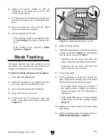
Page 30: ...own in Figure 29 and around the bottom wheel Figure 28 Tension handle and blade Figure 29 Installing blade 6 Hold the blade around the bottom wheel with one hand and slip it around the top wheel with...

Page 31: ...ide assemblies 11 Adjust the blade guides as needed Refer to Blade Guide Bearings on Page 32 8 Tighten the tension handle as tight as necessary so the blade will not slip on the wheels during start up...

Page 32: ...he blade Blade Tension Proper blade tension is essential to long blade life straight cuts and efficient cutting The Model G9743 features a blade tension indicator to assist you with blade tensioning T...

Page 33: ...sired clearance The bearing and blade should make light contact or have a clearance of 0 001 0 002 5 Tighten the nut to lock the eccentric bushing and bearing in position Figure 33 Blade guide adjustm...

Page 34: ...ration Double check all wires dis connected or connected during any wiring task to ensure tight connections CIRCUIT REQUIREMENTS You MUST follow the requirements at the beginning of this manual when c...

Page 35: ...33 Electrical Components Figure 36 Bandsaw ON and E Stop Switches Figure 38 Coolant pump ON OFF Switch Figure 39 Pump junction box Figure 35 Circuit breaker Figure 37 Auto shutoff switch Figure 40 Mot...

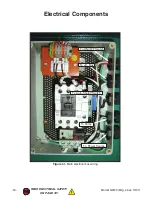
Page 36: ...34 Model G9743 Mfg since 12 07 READ ELECTRICAL SAFETY ON PAGE 33 Electrical Components Figure 41 Main electrical box wiring To Pump To Jct Box To ON OFF Switch To Auto Shutoff Switch To Power Source...

Page 37: ...V2 Ground 1 4 4 3 3 4 1UF 120 Ohm 0 7 L N N N L L Ground Optional 220V Connection Prewired 110V Connection MOTOR MOTOR Main Electrical Box 110 VAC 5 15 Plug Optional 220V Connection 3 4 2 3 2 2 Overl...

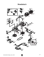
Page 38: ...751 5 751 8 751 6 751 7 76 73 62 100 99 102 98 369 364 365 366 61 370 78 74 75 58 60 63 59 56 57 47 374 368 367 372 375 377 376 373 34 33 31 32 30 1 29 9 43 44 49 51 50 45 46 17 21 24 42 36 41 28 39 3...

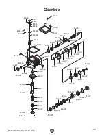
Page 39: ...224 227 230 228 227 224 223 226 229 193 191 190 194 206 204 203 205 197 200 198 196 195 310 316 315 321 317 318 319 320 201 202 294 293 308 308 5 308 3 308 2 308 4 292 290 291 345 341 263 263 1 263 2...

Page 40: ...235 4 235 2 235 10 235 9 235 11 315 1 316 2 316 1 317 1 317 3 317 2 317 11 317 10 292 4 315 3 315 2 294 2 294 1 292 5 317 9 317 8 317 4 293 3 293 2 292 11 293 1 292 10 292 13 292 12 317 7 317 6 317 5...

Page 41: ...800 41 800 54 800 44 800 43 800 45 800 55 800 38 800 39 800 3 800 46 800 1 800 53 800 19 800 50 800 49 800 56 800 57 800 4 800 5 800 6 800 7 800 8 800 19 800 26 800 27 800 18 800 33 800 31 800 21 800...

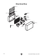
Page 42: ...40 Model G9743 Mfg since 12 07 261V2 1 261V4 2 261V2 3 261 4 261V2 5 261V2 6 261 8 261V2 9 261V2 10 261 11 261 12 261 13 261 16 261 14 261 15 261 18 261 18 261 17 Electrical Box...

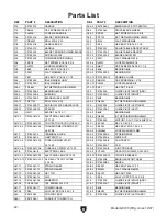
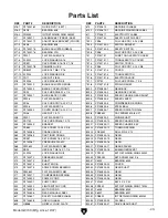
Page 43: ...SHING 95 PW07 FLAT WASHER 5 16 36 P9743036 SUPPORT ROD 96 PB11 HEX BOLT 5 16 18 X 1 1 2 37 PB07 HEX BOLT 5 16 18 X 3 4 97 P0561082 COOLANT TANK 38 P9743038 PIVOT BRACKET 98 P9743098 PUMP 39 P9743039 B...

Page 44: ...P9743235 11 SLIDING PLATE DRAW BLOCK 294 P9743294 GUIDE PIVOT LEFT ASSY 235 12 P9743235 12 SPACER 294 1 P9743294 1 GUIDE PIVOT LEFT 240 H2317 BLADE 104 1 2 X 1 294 2 P608 BEARING 608 261V2 P9743261V2...

Page 45: ...5 P9743800 5 COMPRESSION SPRING 331 PW06 FLAT WASHER 1 4 800 6 P9743800 6 STEEL BALL 332 P9743332 COVER KNOB 1 4 20 X 1 2 800 7 P9743800 7 SPEED INDICATOR DIAL 337 PN06 HEX NUT 1 2 12 800 8 PSB94M CAP...

Page 46: ...3800 50 RIVET 800 41 P9743800 41 BEARING 60205 800 51 P9743800 51 BEARING COVER 800 42 P9743800 42 BEARING SPACER 800 52 PS09M PHLP HD SCR M5 8 X 10 800 43 P9743800 43 COVER 800 53 P9743800 53 GASKET...

Page 47: ...Model G9743 Mfg since 12 07 45 Notes...

Page 48: ...ll be tried in the State of Washington County of Whatcom We shall in no event be liable for death injuries to persons or property or for incidental contingent special or consequential damages arising...

Page 49: ..._____ 0 2 Years _____ 2 8 Years _____ 8 20 Years _ ____20 Years 6 How many of your machines or tools are Grizzly _____ 0 2 _____ 3 5 _____ 6 9 _ ____10 7 Do you think your machine represents a good v...

Page 50: ...LINE FOLD ALONG DOTTED LINE GRIZZLY INDUSTRIAL INC P O BOX 2069 BELLINGHAM WA 98227 2069 Place Stamp Here Name_______________________________ Street_______________________________ City______________S...

Page 51: ......
Page 52: ...ly Trusted Proven and a Great Value OR SECURE ORDERING ORDERS SHIPPED WITHIN 24 HOURS E MAIL RESPONSE WITHIN ONE HOUR Visit Our Website Today And Discover Why Grizzly Is The Industry Leader Call Today...

Reviews: