background image

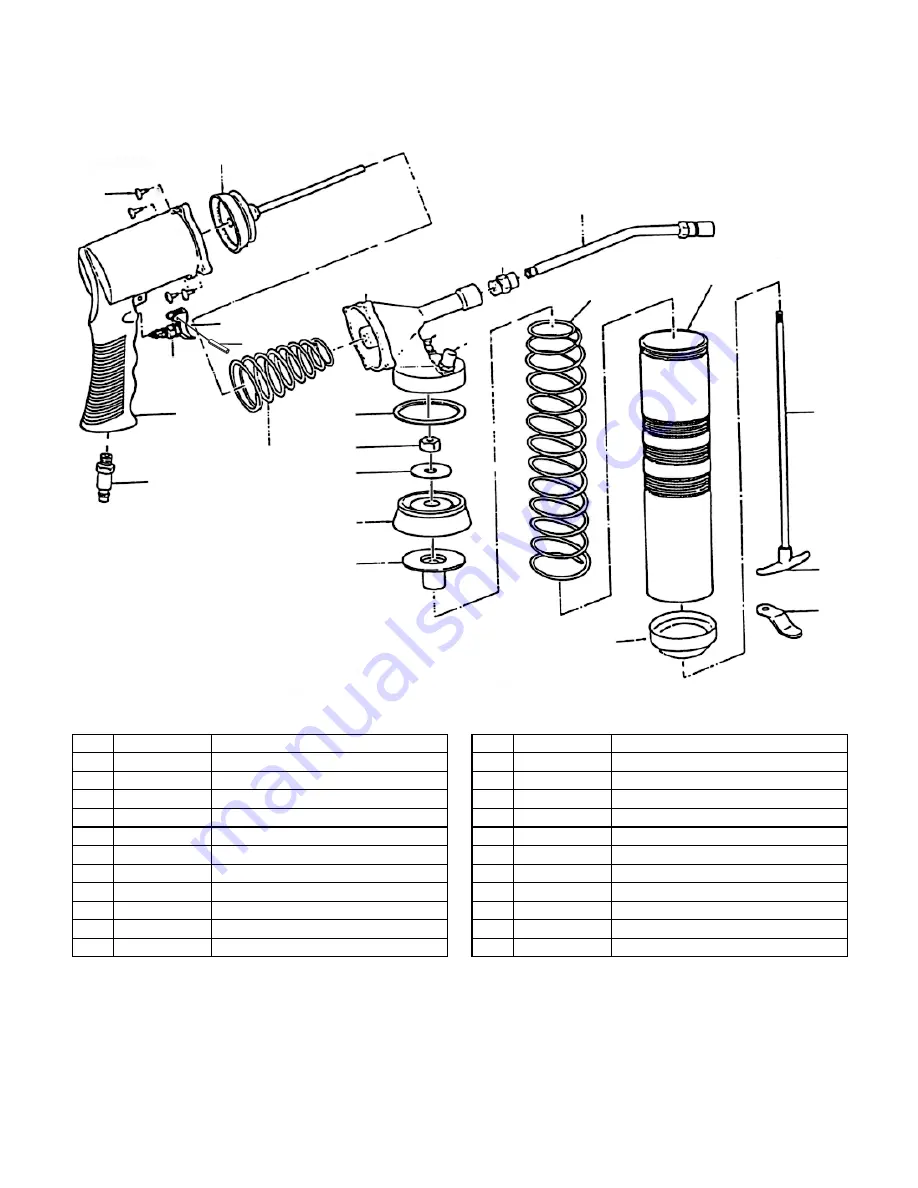
h0580 parts Breakdown and list

&

'

(

("&

)

*

+

,

-

.

&%

&&

&'

&(

&)

&*

&+

&,

&-

&-"&

&.

'%

'&

("'

REF PART #

DESCRIPTION

REF PART #

DESCRIPTION

1

PH0580001

GREASE GUN BODY

11

PH0580011

GREASE INLET

2

PH0580002

1/4" NPT AIR INLET

12

PH0580012

GASKET

3

PH0580003

SWITCH

13

PH0580013

PLUNGER NUT

3-1

PH0580003-1

TRIGGER AND PIN

14

PH0580014

PLUNGER WASHER

3-2

PRP37M

ROLL PIN 3 X 14

15

PH0580015

PLUNGER

4

PH0580004

SPECIAL BODY SCREW

16

PH0580016

BACKLASH GASKET

5

PH0580005

AIR PLUNGER

17

PH0580017

LONG SPRING KIT

6

PH0580006

SHORT SPRING

18

PH0580018

CARTRIDGE TUBE

7

PH0580007

HEAD

18-1

PH0580018-1

BOTTOM CAP

8

PH0580008

ADAPTER

19

PH0580019

FOLLOWER ROD

9

PH0580009

HYDRAULIC COUPLER EXTENSION

20

PH0580020

ROD HANDLE

10

PH0580010

BLEEDER VALVE

21

PH0580021

LOCKING TAB

Summary of Contents for H0580

Page 1: ...at 570 546 9663 Copyright May 2008 By Grizzly Industrial Inc Warning No portion of this manual may be reproduced in any shape Or form without the written approval of Grizzly Industrial inc jm10671 printed in TAIWAN EYE INJURY HAZARD Always wear safety glasses during use to prevent serious personal injury INJURY HAZARD When servicing always dis connect tool from air to pre vent unexpected operation...

Page 2: ...THE AIR SUPPLY NOTICE Some mechanical systems may only require a small amount of grease while others require much more Understand the lubri cation requirements of the part you are lubricating Failure to follow this instruction can damage seals or under lubricate parts causing costly damage 3 Remove the head assembly Figure 1 from the cartridge tube 4 If an empty grease cartridge is in the gun remo...

Page 3: ...elease any air in the head assembly and verify the grease gun works correctly Note If the grease gun does not dispense grease correctly repeat this procedure as many times as necessary Filling from a Bulk Grease Container 1 DISCONNECT THE TOOL FROM THE AIR SUPPLY 2 Pull the follower rod back until it is fully extended the locking tab will automatically hold it in place Figure 4 3 Remove the head a...

Page 4: ...IN 14 PH0580014 PLUNGER WASHER 3 2 PRP37M ROLL PIN 3 X 14 15 PH0580015 PLUNGER 4 PH0580004 SPECIAL BODY SCREW 16 PH0580016 BACKLASH GASKET 5 PH0580005 AIR PLUNGER 17 PH0580017 LONG SPRING KIT 6 PH0580006 SHORT SPRING 18 PH0580018 CARTRIDGE TUBE 7 PH0580007 HEAD 18 1 PH0580018 1 BOTTOM CAP 8 PH0580008 ADAPTER 19 PH0580019 FOLLOWER ROD 9 PH0580009 HYDRAULIC COUPLER EXTENSION 20 PH0580020 ROD HANDLE ...

Reviews: