2.
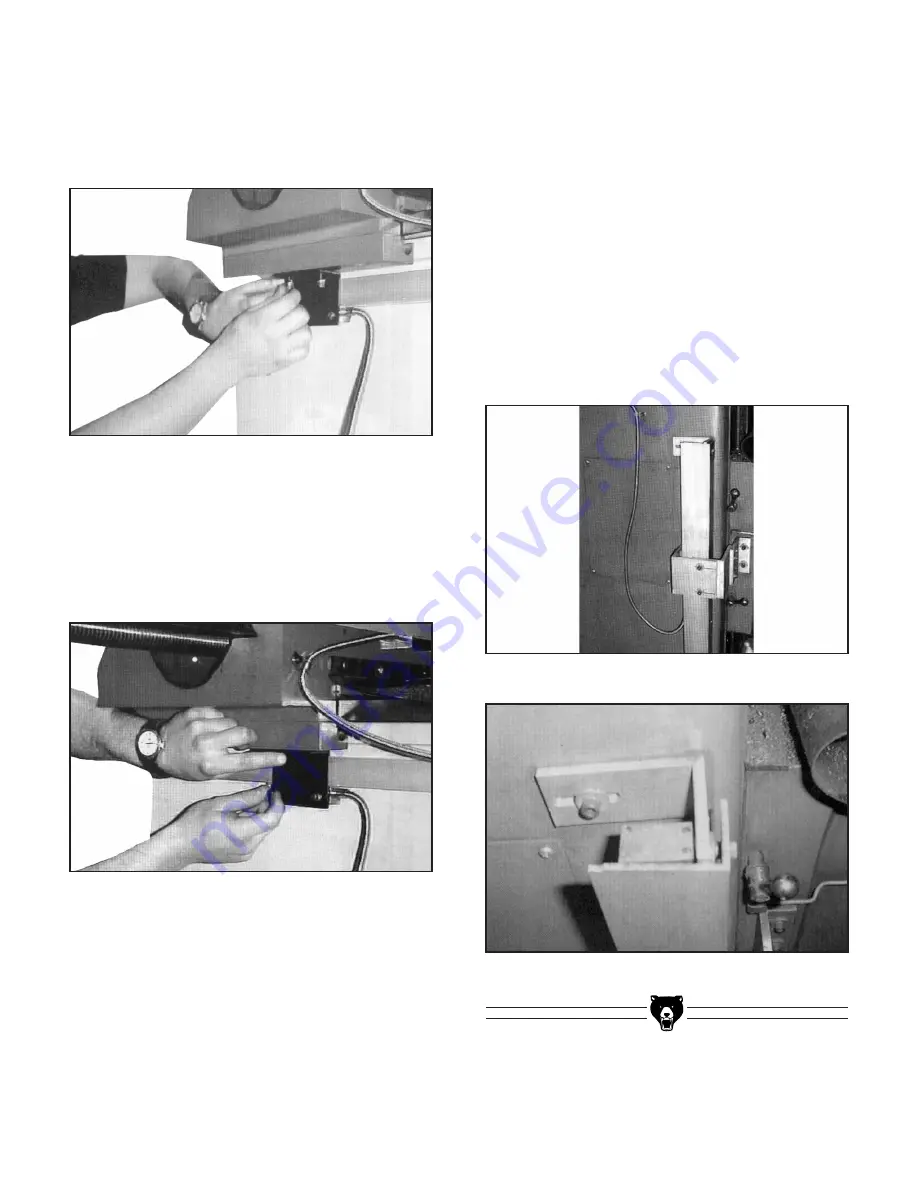
Mount the bracket on the saddle (
Figure 19
),
to accept the reader head, making sure that
the reader head is in-line and parallel to the
scale. Secure the cable and leave enough
free cable to allow for the travel of the slide.
Figure 19.
Mounting the bracket to the saddle.
Fitting the "Z" axis scale:
Before mounting the "Z" axis scale, ensure that it
will read "+" as you wind the table down, increas-
ing the distance from the table to the cutter.
1.
The "Z" axis scale should be installed on the
side of the column, ensuring that the open
side of the scale is away from the direct metal
shavings and coolant and that the travel is
in the right direction, "–" towards the spindle
and "+" away from the spindle. The bracket
should be mounted on the knee (
Figure 21
),
and around the scale to allow for the cover to
protect the scale (
Figure 22
), where exces-
sive coolant and metal shavings are present.
3.
After the scale is aligned to the axis, drill and
tap the saddle to suit the provided bracket
and mount the bracket as shown in
Figure
20.
Ensure the reader head is sitting correctly
so when it is attached it will be square and
parallel to the scale.
Figure 20.
Mounting the provided bracket.
Figure 21.
Bracket mounting location.
Figure 22.
Mounted scale cover.
-8-
Digital Readout System
Summary of Contents for H6087
Page 15: ... 10 Digital Readout System ...
Page 16: ......


