background image

-18-

Model h7507 (Mfg. since 3/05)

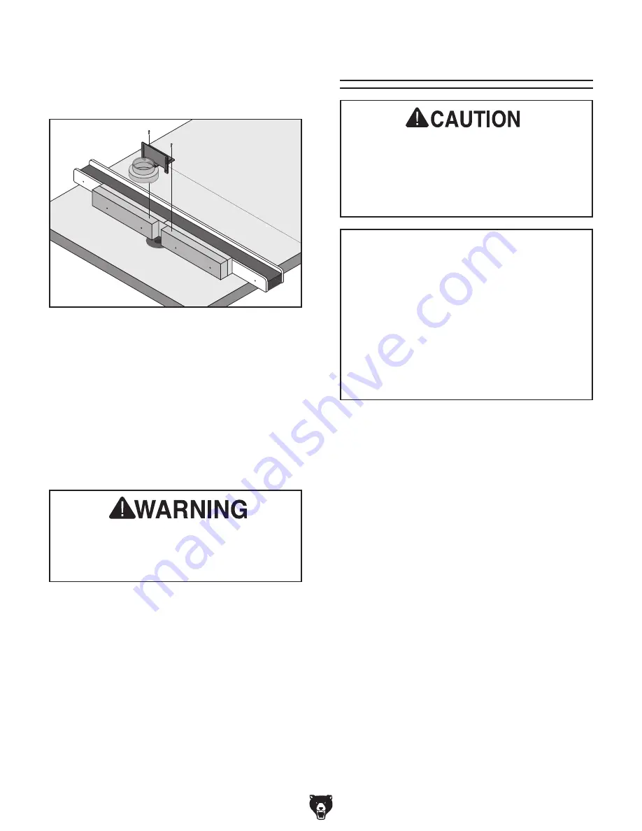
figure 29. attaching router guard.

20.  adjust  the  guard  horizontally  (if  necessary) 

by  using  the  horizontal  bracket  slots  and 
wood screws.

21.  adjust the height of the guard 

1

8

" higher than 

the  workpiece  height  by  using  the  vertical 
bracket slots and carriage bolt/wing nuts.

22.  Connect the top of the guard to your dust col-

lection system with a 3" adapter.

If  you  change  router  bits,  the  fence  pieces 

must be adjusted in/out so there is not more 

than 

1

8

"  clearance  between  the  router  bit 

and the fences.

Dust collection

DO NOT use the Model H7507 without an ade-

quate  dust  collection  system.  An  attached 

router  will  create  substantial  amounts  of 

wood  dust  while  operating.  failure  to  use  a 

dust  collection  system  can  result  in  short 

and long-term respiratory illness.

Recommended cfM at Dust port: 225 cfM
Do not confuse this CFM recommendation with 
the rating of the dust collector. To determine the 
CFM at the dust port, you must consider these 
variables:  (1)  CFM  rating  of  the  dust  collector, 
(2) hose type and length between the dust col-
lector and the machine, (3) number of branches 
or  wyes,  and  (4)  amount  of  other  open  lines 
throughout  the  system.  Explaining  how  to  cal-
culate  these  variables  is  beyond  the  scope  of 
this  manual.  Consult  an  expert  or  purchase  a 
good dust collection "how-to" book.

the Model h7507 features a clear 3" plastic guard 
that can be connected to a dust collector or a dust 
collection system.

19.  Center the guard over the table opening and 

attach  the  guard  assembly  to  the  top  of  the 
fence  boards  with  the  two  provided  wood 
screws, as shown in 

figure 29.

Summary of Contents for H7507

Page 1: ...ER 2010 By Grizzly Industrial Inc Warning No portion of this manual may be reproduced in any shape Or form without the written approval of Grizzly Industrial inc For models manufactured since 3 05 BL13275 printed IN TAIWAN Model H7507 Shown Installed on Model G1023RLW ...

Page 2: ...PERSONAL PROTECTIVE EQUIPMENT 4HE MANUFACTURER WILL NOT BE HELD LIABLE FOR INJURY OR PROPERTY DAMAGE FROM NEGLIGENCE IMPROPER TRAINING MACHINE MODIFICATIONS OR MISUSE 3OME DUST CREATED BY POWER SANDING SAWING GRINDING DRILLING AND OTHER CONSTRUCTION ACTIVITIES CONTAINS CHEMICALS KNOWN TO THE 3TATE OF ALIFORNIA TO CAUSE CANCER BIRTH DEFECTS OR OTHER REPRODUCTIVE HARM 3OME EXAMPLES OF THESE CHEMICAL...

Page 3: ... Setup 7 Unpacking 7 Inventory 8 Hardware Recognition Chart 9 Cleanup 10 Assembly 11 Mounting Router 13 Router Guard 14 Dust Collection 18 SECTION 3 OPERATIONS 19 Operation Overview 19 Workpiece Inspection 20 Table Inserts 20 Edge Jointing 20 Groove Cutting 22 Routing Small Stock 22 Free Hand Routing 23 SECTION 4 MAINTENANCE 25 Schedule 25 Cleaning 25 Unpainted Cast Iron 25 SECTION 5 PARTS 26 Main...

Page 4: ...Zl bVX cZ LZ kZ bVYZ ZkZgn Z dgi id WZ ZmVXi l i i Z chigjXi dch heZX XVi dch YgVl c h VcY e did gVe h d i Z bVX cZ lZ jhZY l Zc lg i c i h bVcjVa dlZkZg hdbZi bZh lZ hi aa bV Z Vc dXXVh dcVa b hiV Z 6ahd dl c id djg eda Xn d Xdci cjdjh begdkZ bZci your machine may not exactly match the manual ndj cY i h id WZ i Z XVhZ VcY i Z Y ZgZcXZ WZilZZc i Z bVcjVa VcY bVX cZ aZVkZh ndj c YdjWi bbZY ViZan XV...

Page 5: ...entification To reduce the risk of serious injury when using this machine read and understand this entire manual before beginning any operations Leg Shop Made Fence Router Not Included Guard Router Bit Not Included Foot Router Table ...

Page 6: ...g deZgViZ jcYZg i Z c ajZcXZ d Ygj h dg VaXd da l Zc i gZY dg l Zc Y higVXiZY OWNER S MANUAL GZVY VcY jcYZghiVcY i h dlcZg h bVcjVa 7 DG jh c bVX cZ JcigV cZY jhZgh XVc WZ hZg djhan jgi EYE PROTECTION 6alVnh lZVg 6CH VeegdkZY hV Zin aVhhZh dg V VXZ h ZaY l Zc deZgVi c dg dWhZgk c bVX cZgn id gZYjXZ i Z g h d ZnZ c_jgn dg Wa cYcZhh gdb an c eVgi XaZh kZgnYVn ZnZ aVhhZh VgZ cdi VeegdkZY hV Zin aVhhZ...

Page 7: ...Z i Z bVX cZ FEED DIRECTION JcaZhh di Zgl hZ cdiZY ZZY ldg V V chi i Z gdiVi dc d WaVYZh dg XjiiZgh ZZY c c i Z hVbZ Y gZXi dc d gdiVi dc bVn ejaa ndjg VcY cid i Z Xji FORCING MACHINERY 9d cdi dgXZ bVX cZ i l aa Yd i Z _dW hV Zg VcY WZiiZg Vi i Z gViZ dg l X i lVh YZh cZY GUARDS COVERS jVgYh VcY XdkZgh XVc egdiZXi ndj gdb VXX YZciVa XdciVXi l i bdk c eVgih dg an c YZWg h BV Z hjgZ i Zn VgZ egde Zg...

Page 8: ...ver force materials past the router Let the cutter do the work Excessive force is likely to result in poor cutting and may cause kickback or serious personal injury APPROPRIATE WORKPIECES The danger of kickback and injury is increased when the workpiece has knots holes or foreign objects in it Warped stock should be properly squared up with a jointer and planer before routing BLIND CUTTING Keep th...

Page 9: ...e filing a freight claim can be difficult When you are completely satisfied with the condi tion of your shipment inventory the contents Unpacking This machine and its com ponents are very heavy Get lifting help or use power lifting equipment such as a forklift to move heavy items The following are needed to complete the setup process but are not included with the router table Additional tools may ...

Page 10: ...ble Hex Bolts 3 8 16 x 11 4 Rtr Main Table 3 Lock Washers 3 8 Rtr Main Table 3 Flat Washers 3 8 Rtr Main Table 3 Hex Bolts 3 8 16 x 11 4 Rtr Table Rail 2 Lock Washers 3 8 Rtr Table Rail 2 Flat Washers 3 8 Rtr Table Rail 4 Hex Nuts 3 8 16 Rtr Table Rail 2 Flat Head Screws 1 4 20 x 3 4 Rail Leg 4 Flat Washers 1 4 Rail Leg 2 Hex Nuts 1 4 20 Rail Leg 2 Guard Phillips Head Screws 8 32 x 5 8 2 Flat Wash...

Page 11: ...Model H7507 Mfg since 3 05 9 Hardware Recognition Chart ...

Page 12: ...ZVcZg YZ gZVh Zg h Z ZXi kZ i Z gjhi egZkZciVi kZ l aa l eZ d ZVh an Note To clean off thick coats of rust preven tative on flat surfaces such as tables use a PLASTIC paint scraper to scrape off the majority of the coating before wiping it off with your rag Do not use a metal scraper or you may scratch your machine 4 GZeZVi Steps 2 3 Vh cZXZhhVgn jci a XaZVc i Zc XdVi Vaa jceV ciZY hjg VXZh l i V ...

Page 13: ...aZ BV c IVWaZ Figure 5 Example of mounting route table to table saw 3 With the help of another person to hold the router table align the mounting holes in both tables and secure them together with the 3 3 8 16 x 11 4 bolts 3 3 8 lock washers and 3 3 8 flat washers as shown in Figure 5 Finger tighten 4 Place the straightedge across the saw table and router table to make sure that the com bined tabl...

Page 14: ...of two legs secured to rail for supporting router table IVeZ Figure 7 Positioning the tape to shim the router table down If the outside edge of the router table tilts up place strips of masking tape along the top edge of the saw table to shim the router table down and even with the saw table from side to side see Figure 7 Note After reinstalling the router table remove all excess masking tape with...

Page 15: ... knobs and adjustment bolts to secure the router in place see Figure 13 If the router unexpectedly moves or the router bit contacts the table insert or fence during operation serious personal injury could result from flying debris ALWAYS make sure that at least three router clamps are used and are applied to a flat surface of the router base before connecting the router to power 4 Install the rema...

Page 16: ...an one fence will be necessary to safely accommodate various sized router bits To make a shop made fence and install the router guard 1 Make a support board with a piece of 11 2 stock approximately 28 long cut to 21 2 tall and square up on all sides Figure 15 Figure 15 Support board dimensions 8ZciZg Ed ci BVg ZY Figure 17 Center point marked on support board 3 Mark the center point of the length ...

Page 17: ...ximately 1 4 deep with a 3 8 drill bit as shown in Figure 19 STEP 7 9g aa daZh i gdj i Z hjeedgi WdVgY STEP 8 8djciZgh c i Z daZh Veegdm bViZan YZZe l i V Yg aa W i VXZ Ide K Zl Figure 19 Steps for drilling and countersinking screw holes into support board 9 Re attach the fence face at both ends as shown in Figure 20 Figure 20 Reattaching fence face 10 Attach the support board to the fence with th...

Page 18: ...moving more than 1 16 from the infeed fence may greatly increase the risk of kick back injury when routing If you are using a router bit that will remove the entire face of the workpiece as illus trated in Figure 24 continue with Step 13 12 Cut your fence in half One side will be the infeed fence and the other side will be the outfeed fence If you are using a router bit that will not remove the en...

Page 19: ...ure 26 18 Assemble the router guard with the compo nents shown in Figure 28 Note If you followed Step 13 be sure to install the modified board on the infeed side c ZZY H YZ Dji ZZY H YZ Figure 27 Attaching fence boards E ae Y HXg m 8Vgg V Z 7dai m L c Cji aVi LVh Zg aVi LVh Zg aVi LVh Zg jVgY AdX LVh Zg Zm Cji KZgi XVa 7gVX Zi dg odciVa 7gVX Zi aVi LVh Zg LddY HXgZl m Figure 28 Assembling router g...

Page 20: ...g Failure to use a dust collection system can result in short and long term respiratory illness Recommended CFM at Dust Port 225 CFM Do not confuse this CFM recommendation with the rating of the dust collector To determine the CFM at the dust port you must consider these variables 1 CFM rating of the dust collector 2 hose type and length between the dust col lector and the machine 3 number of bran...

Page 21: ...and then pushes the workpiece into the bit at a steady and controlled rate until the workpiece moves completely beyond it Important The operator is very careful to keep the workpiece firmly against the table and fence during the entire cut For smaller workpieces or odd shaped workpieces a zero clearance fence or jig is used 9 Stops the router Damage to your eyes lungs and ears could result from us...

Page 22: ...ces with slight cup ping can be safely supported if the cupped side is facing the table or the fence A workpiece supported on the bowed side will rock during a cut and could cause kickback or severe injury Workpiece Inspection Jointing the edge of a board involves using a straight cutting router bit to remove wood from the face of the board The result is a perfectly flat and square edge To joint t...

Page 23: ...r clarity 9 Lock the fence assembly in place adjust the router guard as needed and secure it con nect the router to power then perform the cut see Figure 31 Ide K Zl 8jii c 9 gZXi dc Figure 31 Edge jointing guard removed for clarity Always feed the workpiece against the rout er bit rotation direction as illustrated below Otherwise the workpiece could be aggres sively pulled from your hands drawing...

Page 24: ...tions in Figures 32 33 6 Lock the fence assembly in place adjust the router guard as needed and secure it con nect the router to power then perform the cut Feeding small stock past the router bit is always dangerous If you must route small stock use a zero clearance fence This will provide greater protection for the operator better workpiece sup port and reduced tear out on narrow or fragile stock...

Page 25: ... l c Figure 35 Illustration of free hand cutting with a starting block Irregular or free hand routing as illustrated in Figures 35 takes a high degree of skill and dex terity and is done without the protection and aid from the fence and guard The most dangerous part of free hand routing is beginning the cut where the cutter first contacts the workpiece Often the workpiece will tend to jerk or kick...

Page 26: ...le 4 Fabricate and mount a custom guard over the bit that safely protects your hands from the spinning cutter 5 Clamp a starting block to the table see Figure 36 on the previous page for an exam ple IZbeaViZ GdjiZg IVWaZ 7ZVg c Ldg e ZXZ Figure 37 Using a template and a bearing for free hand routing 7 Connect the router to power and turn it ON 8 Rest the jig with the workpiece attached against the...

Page 27: ...could hamper the safe operation of this router table attach ment Schedule Cleaning the Model H7507 is relatively easy Vacuum excess wood chips and sawdust and wipe off the remaining dust with a dry cloth If any resin has built up use a resin dissolving cleaner to remove it Treat all unpainted cast iron and steel with a non staining lubricant after cleaning Cleaning Protect the unpainted cast iron ...

Page 28: ...7507007 ADJUSTABLE FOOT 30 2 PWN02 WING NUT 1 4 20 8 PN41 HEX NUT 1 2 12 30 3 PH7507030 3 WOOD SCREW 8 X 3 4 9 PH7507009 ROUTER CLAMP 30 4 P1023SLW620 4 HORIZONTAL BRACKET 10 PH7507010 HOLD DOWN KNOB 1 4 20 30 5 PH7507022 VERTICAL BRACKET 11 P0528223 T BOLT 1 4 20 X 2 30 6 PCB18 CARRIAGE BOLT 1 4 20 X 1 2 12 PN05 HEX NUT 1 4 20 30 7 PH7507021 CLEAR GUARD 12A PB31 HEX BOLT 1 4 20 X 1 30 8 PW08 FLAT...

Page 29: ...Vgh TTTT NZVgh TTTT NZVgh 6 dl bVcn d ndjg bVX cZh dg iddah VgZ g ooan4 TTTT TTTT TTTT TTTT 7 9d ndj i c ndjg bVX cZ gZegZhZcih V ddY kVajZ4 TTTTTNZh TTTTTCd 8 LdjaY ndj gZXdbbZcY g ooan cYjhig Va id V g ZcY4 TTTTTNZh TTTTTCd 9 LdjaY ndj Vaadl jh id jhZ ndjg cVbZ Vh V gZ ZgZcXZ dg g ooan XjhidbZgh c ndjg VgZV4 Note We never use names more than 3 times TTTTTNZh TTTTTCd 10 8dbbZcih _________________...

Page 30: ...DI HI6EA DA9 6ADC 9DII 9 A C DA9 6ADC 9DII 9 A C 2 9 5342 0 8 7 EaVXZ HiVbe ZgZ CVbZTTTTTTTTTTTTTTTTTTTTTTTTTTTTTTT HigZZiTTTTTTTTTTTTTTTTTTTTTTTTTTTTTTT 8 inTTTTTTTTTTTTTTHiViZTTTTTTO eTTTTTT HZcY V g ooan 8ViVad id V g ZcY ...

Page 31: ...n h Vaa WZ ig ZY c i Z HiViZ d LVh c idc 8djcin d L ViXdb LZ h Vaa c cd ZkZci WZ a VWaZ dg YZVi c_jg Zh id eZghdch dg egdeZgin dg dg cX YZciVa Xdci c Zci heZX Va dg XdchZfjZci Va YVbV Zh Vg h c gdb i Z jhZ d djg egdYjXih Id iV Z VYkVciV Z d i h lVggVcin XdciVXi jh Wn bV a dg e dcZ VcY kZ jh Vaa i Z YZiV ah LZ l aa i Zc hhjZ ndj V GZijgc CjbWZg l X bjhi WZ XaZVgan edhiZY dc i Z djih YZ Vh lZaa Vh i...

Page 32: ...Buy Direct and Save with Grizzly Trusted Proven and a Great Value Since 1983 ORDER 24 HOURS A DAY 1 800 523 4777 Visit Our Website Today For Current Specials ...

Reviews: