background image

Model H8235  3-Piece Framing/Brad/Palm Nailer Kit

-11

-

Depending on the type of stock and nails 
you  are  using,  it  may  be  necessary  to 
adjust the depth of nail penetration for your 
framing nailer.

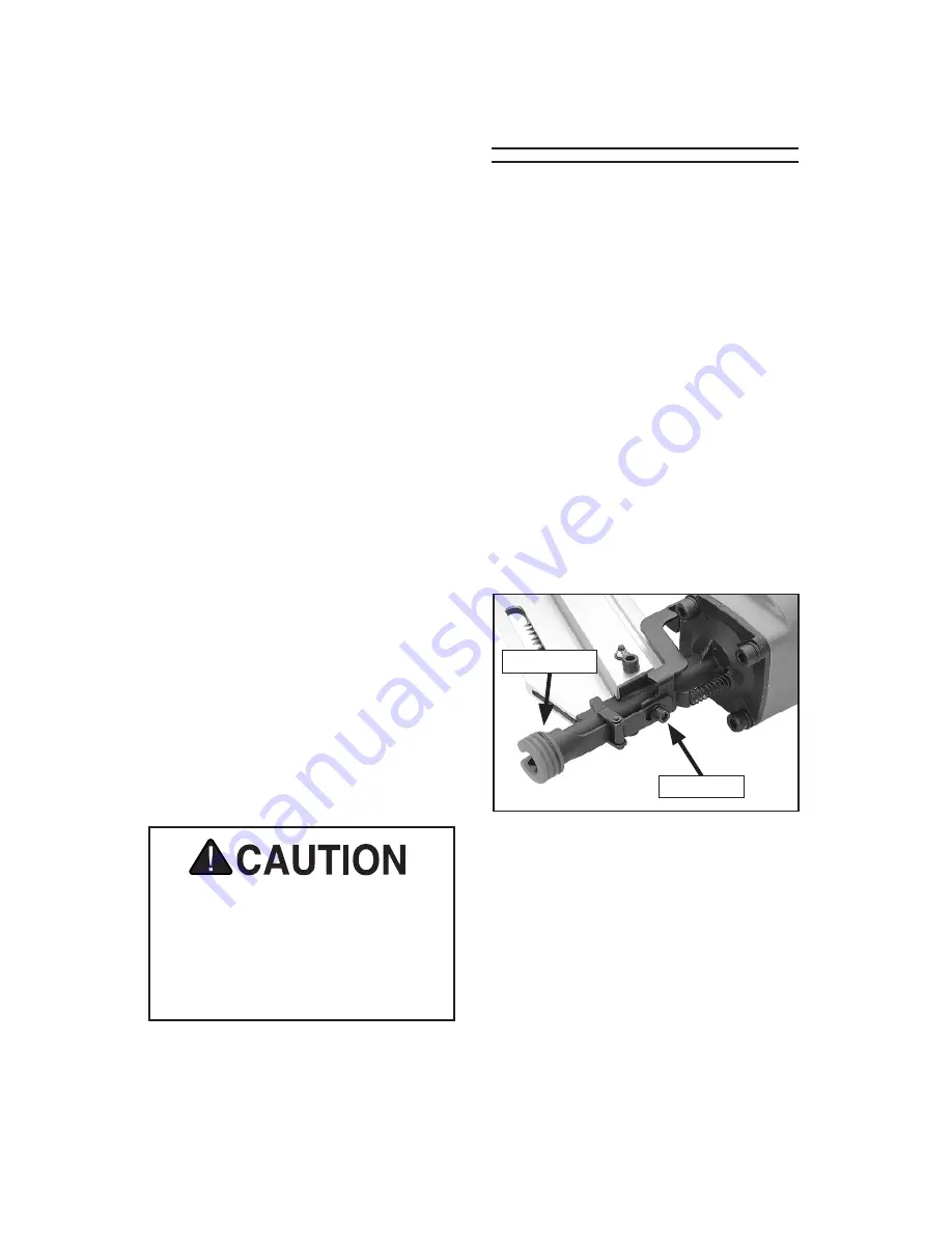
To  adjust  the  depth  for  your  framing 
nailer:

1. 

DISCONNECT  NAILER  FROM  THE 
AIR SUPPLY!

2.

  Use  a  4mm  hex  wrench  to  loosen  the 

cap screw shown in 

Figure 8

.

3.

  Move  the  safety  nose  away  from  the 

nailer body to decrease nail depth, and 
toward the nailer body to increase nail 
depth. 

Adjusting Framing 

Nailer Depth

4.

  Re-tighten the cap screw, then connect 

the nailer to the air supply and test the 
nail depth.

5.

  Repeat 

Steps  2–4

,  if  necessary,  until 

the nail depth is satisfactory.

Figure 8.

 Loosening cap screw for depth 

adjustment.

Safety Nose

Cap Screw

Palm Nailer

1.

  Connect the air supply to the quick con-

nect fitting.

2.

  Make  sure  your  free  hand  and  other 

body  parts  are  positioned  out  of  the 
way of a potential path of a nail in case 
of deflection.

3.

  Hold  the  nail  firmly  in  place  with  one 

hand as if using a regular hammer.

4.

  Place  the  tip  of  the  palm  nailer  over 

the  top  of  the  nail.  When  the  ram  pin 
touches  the  nail  head,  the  nailer  will 
automatically begin to hammer the nail 
into place.

5.

  Hold the nailer in place until the sliding 

depth  guide  is  completely  depressed 
up  into  the  nailer  and  the  nail  is  fully 
hammered into the workpiece.


Note: 

You  can  stop  the  nailer  at  any 

time  by  simply  lifting  it  away  from 
the  nail.  This  is  useful  if  you  do  not 
want  to  countersink  the  nail  into  the 
workpiece.


If  the  nailer  is  allowed  to  continue 
hammering until it stops by itself, it will 
countersink the nail to an approximate 
depth of 2mm or 

5

64

".

DO NOT attempt to adjust the depth on 
your brad nailer. The nose of the brad 
nailer is not designed to be adjusted. 
Doing so could cause the safety nose 
mechanism to malfunction and cause 
personal injury.

Summary of Contents for H8235

Page 1: ...LY INDUSTRIAL INC WARNING NO PORTION OF THIS MANUAL MAY BE REPRODUCED IN ANY SHAPE OR FORM WITHOUT THE WRITTEN APPROVAL OF GRIZZLY INDUSTRIAL INC TS9832 PRINTED IN CHINA MODEL H8235 3 PIECE FRAMING BR...

Page 2: ......

Page 3: ...to do a job for which it was not designed 9 DO NOT USE UNDER THE INFLUENCE OF DRUGS OR ALCOHOL For Your Own Safety Read Instruction Manual Before Operating This Equipment The purpose of safety symbol...

Page 4: ...ng accessories 16 REDUCE THE RISK OF UNINTENTIONAL FIRING Do not carry tool with hand on trigger and always disconnect from air when not in use 17 DISCONNECT TOOLS before servicing changing accessorie...

Page 5: ...4 MODIFICATIONS DO NOT modify this tool or bypass the safety nose mechanism 5 CHECK VALVE Do not use a check valve or any other fitting that allows air to remain in the tool 6 HOSE USAGE Make sure you...

Page 6: ...in serious personal injury Nailer accidents routinely happen while moving the gun to another location such as up ladders to another room or even another job site Always disconnect the gun immediately...

Page 7: ...ssure 70 100 PSI Maximum Air Pressure 120 PSI The specifications details and photo graphs in this manual represent the Model H8235 as supplied when the manual was prepared However owing to Grizzly s p...

Page 8: ...r Palm Nailer Pouch 1 Your new nailer kit was carefully pack aged for safe shipping If you discover any damage after you have signed for deliv ery immediately call Customer Service at 570 546 9663 for...

Page 9: ...l protect your tool from damaging water build up allow you to adjust and maintain constant air pressure to your tool and save you the inconvenience of having to manually lubricate your tool every time...

Page 10: ...gainst a scrap piece of wood that is clean and free of any knots nails or other foreign objects If the nailer does not fire then the safety nose mechanism is working correctly If the nailer does fire...

Page 11: ...n Figure 3 3 Insert a strip or two of nails pointed end down into the magazine as shown in Figure 4 4 Tilt the nailer to slide the nails all the way down to the nose 5 With one hand on the magazine pu...

Page 12: ...5 Slide the nails all the way down to the nose of the nailer 6 Push the magazine cover forward until the magazine latch locks it in place 5 Pull the trigger If the nail drove into the wood far enough...

Page 13: ...our free hand and other body parts are positioned out of the way of a potential path of a nail in case of deflection 3 Hold the nail firmly in place with one hand as if using a regular hammer 4 Place...

Page 14: ...catch lever and slowly let the pusher slide to the front of the magazine Figure 9 Nose opening for clearing a jammed nail Nose Opening Brad Nailer To clear a jammed nail from the dis charge area 1 DIS...

Page 15: ...LY 2 Remove all nails from the magazine cartridge and clean the exterior of the nailer 3 Remove the four cap screws on the back of the nailer near the exhaust port 4 Remove the cap 5 The top of the pi...

Page 16: ...h to remove the four cap screws on the nailer cap then remove the cap 4 Push the ram pin towards the inside of the nailer this will push the cylinder free of the housing 5 Grab the ram pin and pull th...

Page 17: ...Figure 15 before every use or after 2 hours of continuous use Wipe off any excess oil near the nailer exhaust to avoid dust build up When the oil that was included with the nailer has been completely...

Page 18: ...Model H8235 3 Piece Framing Brad Palm Nailer Kit 16 H8235 PARTS Framing Nailer Parts Breakdown...

Page 19: ...AP SCREW M4 7 X 10 23 PH7665023 OUTER BUMPER 71 PW05M FLAT WASHER 4MM 24 PH7665024 BUMPER 72 PN04M HEX NUT M4 7 25 PH7665025 CYLINDER GASKET 73 PH7665073 RELEASE LATCH 26 PH7665026 NAILER BODY 74 PH76...

Page 20: ...Model H8235 3 Piece Framing Brad Palm Nailer Kit 18 Brad Nailer Parts Breakdown...

Page 21: ...CYINDER SLEEVE 147 PH8235147 MAGAZINE CAP 115 PORP029 5 O RING 29 2 X 3 5 P29 5 148 PH8235148 BRACKET 116 PORS042 O RING 2 0 X 41 5 S42 149 PSB41M CAP SCREW M4 7 X 14 117 PH8235117 CYLINDER 150 PH8235...

Page 22: ...1 4 NPT 205 PH6141005 GASKET 219 PH6141019 SPECIAL WASHER 9 X 20 X 1 206 PORPG050 O RING 54 4 X 3 1 G50 220 PH6141020 COMPRESSION SPRING 207 PH6141007 CYLINDER COLLAR 221 PH6141021 DEPTH GUIDE 208 PH...

Page 23: ...repair damage 5 Check fitting hose com pressor air pressure 6 Replace piston O ring Lubricate 7 Replace trigger valve O rings 8 Replace bumper 9 Replace cap seal Tool runs slowly or has a loss of pow...

Page 24: ...ies to persons or property or for incidental contingent special or consequential damages arising from the use of our products To take advantage of this warranty contact us by mail or phone and give us...

Reviews: