background image

TAPE ALONG EDGES--PLEASE DO NOT STAPLE

FOLD ALONG DOTTED LINE

FOLD ALONG DOTTED LINE

GRIZZLY INDUSTRIAL, INC.

P.O. BOX 2069

BELLINGHAM, WA  98227-2069

Place

Stamp

Here

Name_______________________________
Street_______________________________
City______________State______Zip______

Send a Grizzly Catalog to a friend:

Summary of Contents for Polar Bear G0833P

Page 1: ...E OWNER S MANUAL For models manufactured since 06 17 COPYRIGHT JUNE 2017 BY GRIZZLY INDUSTRIAL INC WARNING NO PORTION OF THIS MANUAL MAY BE REPRODUCED IN ANY SHAPE OR FORM WITHOUT THE WRITTEN APPROVAL...

Page 2: ...g grinding tool integrity and the usage of personal protective equipment The manufacturer will not be held liable for injury or property damage from negligence improper training machine modifications...

Page 3: ...37 Ripping 38 Crosscutting 39 Miter Cuts 39 Blade Tilt Bevel Cuts 40 Dado Cutting 40 Rabbet Cutting 42 Resawing 44 SECTION 5 SHOP MADE SAFETY ACCESSORIES 49 Featherboards 49 Push Sticks 52 Push Block...

Page 4: ...machine We made every effort to be exact with the instruc tions specifications drawings and photographs in this manual Sometimes we make mistakes but our policy of continuous improvement also means t...

Page 5: ...to instructions on reducing risk of kickback f Do not perform any operation freehand g Never reach around or over saw blade Identification Become familiar with the names and locations of the controls...

Page 6: ...each handwheel C Blade Tilt Handwheel Adjusts angle of blade tilt from 90 45 D Blade Height Handwheel Adjusts blade height from 0 31 8 Figure 2 Blade adjustment handwheels and locks Figure 1 Location...

Page 7: ...to Page 49 for more details Kerf The resulting cut or gap in the workpiece after the saw blade passes through during a cutting operation Kickback An event in which the workpiece is propelled back tow...

Page 8: ...1 Type Cardboard Box on Wood Skids Content Machine Weight 388 lbs Length x Width x Height 30 x 25 x 42 in Must Ship Upright Yes Carton 2 Type Cardboard Box Content Fence Weight 21 lbs Length x Width...

Page 9: ...uded Fence Rails 31 1 2 in Max Rip Left of Blade w Included Fence Rails 11 3 8 in Additional Blade Information Included Blade Information 10 x 40T Riving Knife Spreader Thickness 0 1 in Required Blade...

Page 10: ...s 2 Dust Port Size 4 in 1 1 2 in Compatible Mobile Base D2057A Other Specifications Country of Origin China Warranty 1 Year Approximate Assembly Setup Time 1 Hour Serial Number Location Machine ID Lab...

Page 11: ...proof DANGEROUS ENVIRONMENTS Do not use machinery in areas that are wet cluttered or have poor lighting Operating machinery in these areas greatly increases the risk of accidents and injury MENTAL ALE...

Page 12: ...moving parts or flying debris Make sure they are properly installed undamaged and working correctly BEFORE operating machine FORCING MACHINERY Do not force machine It will do the job safer and better...

Page 13: ...ons in this manual CUTTING CORRECT MATERIAL Cutting metal glass stone tile etc increases risk of operator injury due to kickback or flying particles Only cut natural and man made wood products laminat...

Page 14: ...ough cut Making a deep non through cut will greatly increase the chance of kickback Preventing Kickback Statistics show that most common acci dents among table saw users can be linked to kickback Kick...

Page 15: ...on a power supply circuit that has a verified ground and meets the requirements listed below Refer to Voltage Conversion instructions for details Availability Before installing the machine consider t...

Page 16: ...result in a risk of electric shock The wire with green insulation with or without yellow stripes is the equipment grounding wire If repair or replacement of the power cord or plug is nec essary do no...

Page 17: ...d for 110V The voltage conversion MUST be performed by an electrician or qualified service personnel The voltage conversion procedure consists of rewiring the motor and installing the correct plug A w...

Page 18: ...e Wear safety glasses during the entire setup process This machine and its components are very heavy Get lifting help or use power lifting equip ment such as a forklift to move heavy items This machin...

Page 19: ...Support 1 Figure 10 Extension wings NOTICE If you cannot find an item on this list care fully check around inside the machine and packaging materials Often these items get lost in packaging materials...

Page 20: ...ear Rail Table 2 AK Flat Washers 10mm Rear Rail Table 2 AL Cap Screws M8 1 25 x 35 Rear Rail Wing 2 AM Flat Washers 8mm Rear Rail Wing 4 AN Lock Washers 8mm Rear Rail Wing 2 AO Hex Nuts M8 1 25 Rear R...

Page 21: ...Model G0833P Mfd Since 06 17 19 Hardware Recognition Chart USE THIS CHART TO MATCH UP HARDWARE DURING THE INVENTORY AND ASSEMBLY PROCESS 5mm 5mm Flat Head Cap Screw...

Page 22: ...per optional Basic steps for removing rust preventative 1 Put on safety glasses 2 Coat the rust preventative with a liberal amount of cleaner degreaser then let it soak for 5 10 minutes 3 Wipe off the...

Page 23: ...required space allocation Physical Environment The physical environment where the machine is operated is important for safe operation and lon gevity of machine components For best results operate thi...

Page 24: ...l listed items To ensure the assembly process goes smoothly first clean any parts that are cov ered or coated in heavy duty rust preventative if applicable 1 Using blade height handwheel refer to Page...

Page 25: ...edge across extension wings and main table to make sure that combined table surface is flat If combined table surface is flat skip to next step If outside end of extension wing tilts down place a stri...

Page 26: ...before completely tightening cap screws 13 Secure rear rail to extension wings with 2 M8 1 25 x 35 cap screws 4 8mm flat wash ers 2 8mm lock washers and 2 M8 1 25 hex nuts see Figure 25 Figure 25 Rea...

Page 27: ...el with miter slot then you MUST adjust fence as described in Fence Adjustments on Page 69 so that it is parallel If miter slot is not parallel with blade you must follow procedures described in Miter...

Page 28: ...mm lock washers and 5mm flat washers as shown in Figure 29 Figure 29 Switch installed 24 Attach dust hose support to rear rail with 1 M6 1 hex nut 6mm flat washer and M6 1 wing nut as shown in Figure...

Page 29: ...his manual Consult an expert or purchase a good dust collection how to book This machine creates a lot of wood chips dust during operation Breathing airborne dust on a regular basis can result in perm...

Page 30: ...green ON START button as shown in Figure 34 Test Run Once assembly is complete test run the machine to ensure it is properly connected to power and safety components are functioning correctly If you...

Page 31: ...overview is to provide the nov ice machine operator with a basic understanding of how the machine is used during operation so the machine controls components discussed later in this manual are easier...

Page 32: ...backer board creates extremely fine dust and may reduce the life of the motor bearings This machine is NOT designed to cut metal glass stone tile etc cutting these materials with a table saw greatly...

Page 33: ...recommendations to ensure safe and efficient operation of your table saw Ripping Blade Features Best for cutting with the grain 20 40 teeth Flat top ground tooth profile Large gullets for large chip r...

Page 34: ...hin Kerf Blade A blade with thinner kerf than a standard blade Since the spreader riving knife included with this table saw is sized for standard blades thin kerf blades cannot be used on this saw unl...

Page 35: ...r wrench DO NOT overtighten 7 Re install table insert see Page 72 and blade guard see Page 34 or riving knife see Page 37 5 Install new blade flange and arbor nut on arbor as shown in Figure 44 with u...

Page 36: ...down to accommodate the height of the workpiece and return to the table surface Spreader The spreader is a metal plate that prevents the newly cut kerf of the workpiece from pinching the backside of...

Page 37: ...properly aligned spreader riving knife will be in Alignment Zone shown in Figure 48 and will be parallel with blade Figure 47 Blade guard installed 8 Install blade guard dust port and dust collec tion...

Page 38: ...narrow workpieces or other specialized cuts Because the blade guard is provided to decrease your risk of injury it should not be used if it gets in the way of making a safe cut Use good judgment Disab...

Page 39: ...o Install the Riving Knife The riving knife is installed in a similar manner to the blade guard and spreader Refer to Blade Guard Assembly on Page 34 for installation instructions To ensure that rivin...

Page 40: ...e that blade guard spreader is installed 5 Loosen fence knobs see Figure 54 remove rip fence then re install in vertical position for thicker workpieces or in horizontal position for thinner workpiece...

Page 41: ...igure 56 Typical crosscutting operation Crosscutting Miter Cuts A miter is an angled crosscut Miters are usually cut in the same manner as crosscuts using the miter gauge and a predetermined mark on t...

Page 42: ...e or a standard saw blade The Figure below shows a cutaway view of a dado cut being made with a dado blade Dado Blade Workpiece Fence The Model G0833P can accommodate dado blades up to 10 in diameter...

Page 43: ...do length of a workpiece If dadoing across workpiece use miter gauge and carefully line up desired cut with dado blade To reduce kickback DO NOT use fence in combination with miter gauge 4 Reconnect s...

Page 44: ...ting operation on other side of dado as shown in Figure 62 8 Make additional cuts see Figure 63 in cen ter of dado to clear out necessary material Dado is complete when channel is complete ly cleared...

Page 45: ...s to reduce risk of kickback Cutting Rabbets with a Standard Blade A ripping blade is typically the best blade to use for cutting rabbets when using a standard blade because it removes sawdust very ef...

Page 46: ...machine for resawing and resawing with one is fairly easy and safe A table saw is not intended for resawing and resawing with one is difficult and dangerous due to the increased risk of kickback from...

Page 47: ...upport for the workpiece This minimizes the probability of it binding against the blade and causing kickback Tools Needed Qty Table Saw 1 Jointer and Planer Recommended Clamps 2 Minimum Drill 1 Drill...

Page 48: ...on auxiliary fence and remove auxiliary fence board from fence tube 5 Using 7 32 drill bit drill mounting holes in auxiliary fence board Countersink holes 1 16 deep so head of flat head cap screws sit...

Page 49: ...edure Stand to the side of the blade and wear safety glasses and a full face shield to prevent injury when resawing 4 Attach auxiliary fence and set it to desired width Note When determining correct w...

Page 50: ...Page 47 Leaving a 1 8 connec tion will reduce risk of kickback 8 Plug in table saw turn it ON and use a push stick or push block to feed workpiece through blade using a slow and steady feed rate Note...

Page 51: ...sign Most featherboards are 10 28 long and 3 6 wide Make sure the wood grain runs paral lel with the length of the featherboard so the fingers you will create in Step 3 will bend without breaking Feat...

Page 52: ...t Side View Wing Nut Miter Bar Featherboard Flat Head Screw Flat Washer Figure 77 Assembling miter slot featherboard components Note The routed slot countersink hole and flat head screw are essential...

Page 53: ...ounting Featherboards w Clamps 4 Secure featherboard to table with a clamp 5 Check featherboard by pushing it with your thumb to ensure it is secure If featherboard moves tighten clamp more 6 Optional...

Page 54: ...ck Push Stick Prohibition Zone Store Push Stick Here for Easy Access Supporting A second push stick can be used to keep the workpiece firmly against the fence while cutting When using a push stick in...

Page 55: ...ing a Push Block A push block can be used in place of or in addi tion to a push stick for feeding workpieces into the blade Due to their design push blocks allow the operator to apply firm downward pr...

Page 56: ...rrow rip auxiliary fence and push block system shown in this section is an example of a specialty jig that can be made to increase the safety of very narrow rip cuts 2 Pre drill and countersink eight...

Page 57: ...Cutting Width Blade Auxilliary Fence Figure 89 Adjusting ripping distance between blade and auxiliary fence Auxilliary Fence Blade Workpiece Push Stick for Side Support Blade Path Push Block Figure 90...

Page 58: ...ickback when crosscutting Figure 93 Example of crosscut sled Crosscut Sled Crosscut Sled One of the best accessories for improving the safety and ease of using a table saw is simply plac ing a large t...

Page 59: ...Figure 94 Dust collection accessories D4206 W1317 D4216 W1007 W1017 W1053 G1163P 1HP Floor Model Dust Collector G0710 1HP Wall Mount Dust Collector H4340 3 0 Micron Upgrade Bag Excellent point of use...

Page 60: ...ip 50T combination and 80T crosscut 5 8 arbor 1 8 kerf Figure 98 Forrest Woodworker II Saw Blade H8029 5 Pc Safety Kit Comes with four table saw jigs essential for safe operation Includes two push blo...

Page 61: ...um performance from your machine follow this maintenance schedule and refer to any specific instructions given in this section Daily Check Loose mounting bolts arbor nut Damaged saw blade Worn or dama...

Page 62: ...3 Worm and bull gear location Bull Gear Worm Gear Figure 104 Leadscrew location Leadscrew Clean away any built up grime and debris from the worm gear bull gear and leadscrew see Figures 103 104 with a...

Page 63: ...ting speed 2 Only cut wood ensure moisture is below 20 3 Clean motor let cool and reduce workload Reset breaker 4 Use correct sharp blade reduce feed rate 5 Tension replace belt s 6 Wire motor correct...

Page 64: ...r teeth 3 Adjust fence parallel with blade Page 70 4 Make miter slot parallel with blade Page 65 5 Adjust riving knife or spreader into alignment with blade Page 67 6 Adjust spreader into alignment wi...

Page 65: ...djustments do not need to be made Make sure tilt indica tor arrow shown in Figure 106 points to 0 mark on scale Adjust position by loosening button head screw moving indicator with your fingers then t...

Page 66: ...ar to move 8 Repeat Steps 2 3 to verify that collar adjust ment you made was correct When adjust ment is satisfactory close motor door 6 Place a 45 square against blade as shown in Figure 108 then adj...

Page 67: ...table square to measure distance from miter slot to a car bide tip on blade as shown in Figure 110 Make sure that face of adjustable square is even along miter slot The saw blade is sharp Use extra ca...

Page 68: ...her with metal shim stock Continue to Step 9 9 Loosen 4 table mounting bolts from Step 6 Mounting Bolts Figure 112 Location of table mounting bolts table omitted for clarity 7 Repeat Steps 2 6 until b...

Page 69: ...y came apart Spreader or Riving Knife Alignment Checking Alignment The blade guard spreader and riving knife must be aligned with the blade when installed If the spreader riving knife is not aligned w...

Page 70: ...ition 1 DISCONNECT MACHINE FROM POWER 2 Remove table insert 3 Loosen 2 capscrewsonmountingblock then adjust either top or bottom control set screws or side control set screws see Figure 117 to move it...

Page 71: ...s There are four main adjustments for the fence height off the table squareness parallelism with the miter slot and clamping pressure These adjustments are interconnected and some repeti tion may be n...

Page 72: ...e is parallel with the miter slot To adjust fence parallelism and clamping pressure 1 DISCONNECT MACHINE FROM POWER 2 Lock fence tap front side with your fist and check to see if it moved sideways ove...

Page 73: ...nd burning The argument is that this offset adjustment reduc es the chance of kickback by alleviating potential binding that may occur between the backside of the blade and fence The tradeoff is sligh...

Page 74: ...23 Fence indicator window Screws Indicator Window Table Dado Insert Adjustment The table dado insert must sit perfectly flush with the table to provide a smooth continuous surface for the workpiece to...

Page 75: ...evenly against face of miter gauge and blade as shown in Figure 126 If square does not touch miter body and blade body evenly at same time then pro ceed to Step 5 5 Loosen button head cap screws on p...

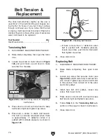
Page 76: ...it will need to be tensioned If the belt is cracked frayed or shows other signs of excessive wear it will need to be replaced Replacing Belt 1 DISCONNECT MACHINE FROM POWER 2 Raise blade completely t...

Page 77: ...t at the time of printing but may not match your machine If you find this to be the case use the wiring diagram inside the motor junction box CAPACITORS INVERTERS Some capacitors and power inverters s...

Page 78: ...As Recommended 115V 230V MOTOR SWITCH BOX Motor Rewired for 115V Motor Prewired for 230V Run Capacitor 40MFD 450VAC GND GND Circuit Breaker KUOYUH 10A 125V 250V ON OFF SWITCH Ground Hot Hot 6 20 PLUG...

Page 79: ...nce 06 17 77 READ ELECTRICAL SAFETY ON PAGE 75 Electrical Components Figure 130 Motor capacitors Figure 131 Motor junction box Figure 132 Switch box components Capacitors Circuit Breaker ON OFF Switch...

Page 80: ...LEADSCREW BRACKET 6 P0833P006 FLAT HD CAP SCR M5 8 X 10 24 P0833P024 BUTTON HD CAP SCR M5 8 X 16 7 P0833P007 TABLE INSERT MAGNET 25 P0833P025 LOCK NUT M8 1 25 8 P0833P008 MAIN TABLE 26 P0833P026 TILT...

Page 81: ...185 186 187 188 192 191 190 189 180 188 187 186 102 194 195 193 120 119 169 170 172 120 196 115 201 134 136 137138 139 108 140 139 108 135 141 142 146 146 149 150 151 152 153 154 155 156 157 159 108...

Page 82: ...173 MOTOR LOCATING SHAFT 116 P0833P116 MOTOR PULLEY 174 P0833P174 STOP COLLAR 117 P0833P117 HEX BOLT M6 1 X 16 175 P0833P175 INT RETAINING RING 24MM 118 P0833P118 LOCK NUT M5 8 176 P0833P176 TILT LEAD...

Page 83: ...8 P0833P228 FLAT WASHER 5MM 222 1 P0833P222 1 PADDLE SWITCH LOCKOUT PIN 229 P0833P229 CLAMP ON TERMINAL RING 223 P0833P223 SWITCH BOX 231 P0833P231 SWITCH BRACKET 224 P0833P224 CIRCUIT BREAKER KUOYUH...

Page 84: ...OULDER SCREW M5 8 X 10 11 X 20 306 P0833P306 LEFT GUARD 324 P0833P324 RIGHT GUARD 307 P0833P307 TAP SCREW M3 5 X 16 325 P0833P325 TAP SCREW M3 X 10 308 P0833P308 SPRING CLAMP 326 P0833P326 RIVING KNIF...

Page 85: ...2 5 X 8 BLIND STEEL 413 P0833P413 BUTTON HD CAP SCR M4 7 X 10 404 P0833P404 SET SCREW M8 1 25 X 6 414 P0833P414 MITER GAUGE POINTER 405 P0833P405 MITER RING 415 P0833P415 FLAT WASHER 4MM 406 P0833P40...

Page 86: ...514 P0833P514 FLAT WASHER 5MM 504 P0833P504 SET SCREW M12 1 75 X 10 515 P0833P515 FENCE SCALE WINDOW 505 P0833P505 HEX BOLT M6 1 X 40 519 P0833P519 FENCE BASE END CAP 50 X 50MM 506 P0833P506 CAM LOCK...

Page 87: ...33P612 REAR FENCE RAIL 603 P0833P603 FRONT FENCE RAIL 613 P0833P613 CAP SCREW M10 1 5 X 25 604 P0833P604 FENCE SCALE LABEL 614 P0833P614 LOCK WASHER 10MM 605 P0833P605 FLAT WASHER 6MM 615 P0833P615 FL...

Page 88: ...or go to www grizzly com WARNING DANGER WARNING CAUTION NOTICE PANTONE 3005 C or RAL 5005 PANTONE 485 C or RAL 3001 COLOR CODES PANTONE 151 C or RAL 2005 PANTONE 109 C Rotating blade adjustment handwh...

Page 89: ...metalworker ____ 0 2 Years ____ 2 8 Years ____ 8 20 Years ____20 Years 6 How many of your machines or tools are Grizzly ____ 0 2 ____ 3 5 ____ 6 9 ____10 7 Do you think your machine represents a good...

Page 90: ...LINE FOLD ALONG DOTTED LINE GRIZZLY INDUSTRIAL INC P O BOX 2069 BELLINGHAM WA 98227 2069 Place Stamp Here Name_______________________________ Street_______________________________ City______________S...

Page 91: ...tried in the State of Washington County of Whatcom We shall in no event be liable for death injuries to persons or property or for incidental contingent special or consequential damages arising from...

Page 92: ......

Reviews: