-4-
Model T32335 (Mfd. Since 11/20)
Controls &
Components
To reduce your risk of
serious injury, read this
entire manual BEFORE
using machine.
Refer to the following figures and descriptions to
become familiar with the basic controls and com-
ponents of this machine. Understanding these
items and how they work will help you understand
the rest of the manual and minimize your risk of
injury when operating this machine.
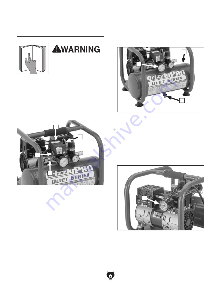
Air Input
F
G
E
Figure 2. Air input components.
E. Tank Pressure Gauge: Indicates pressure
of air in tank.
F. Tank: Holds up to 2 gallons of pressurized
air.
G. Drain Valve: Drains built-up moisture from
tank when ball valve is opened.
H. Air Filter: Cleans air entering compressor
pump.
Figure 3. Location of air filter.
H
Automatic Pressurization
Figure 1. Pressurization components.
A. Pressure Switch: Turns motor ON when
tank pressure drops below 95 PSI (cut-in
pressure) and switch is in AUTO position.
Switch contains pressure relief valve that will
activate discharge line when tank pressure
exceeds 115 PSI (cut-out pressure) or pres-
sure switch is turned
OFF.
B. Discharge Line: Releases air from compres-
sor pump and outlet line when tank pressure
exceeds 115 PSI (cut-out pressure).
C. Safety Relief Valve: Pops open to release
tank pressure in the event that pressure
switch fails to stop motor at cut-out pressure.
B
C
A
D. Pressure Switch Lever: Toggles pressure
switch between OFF and AUTO modes.
Machine is
OFF in OFF mode, and will con-
tinue to pressurize when in AUTO mode.
D
Summary of Contents for QUIET Series
Page 40: ......


