-6-
Model T10157 (Mfd. Since 07/19)
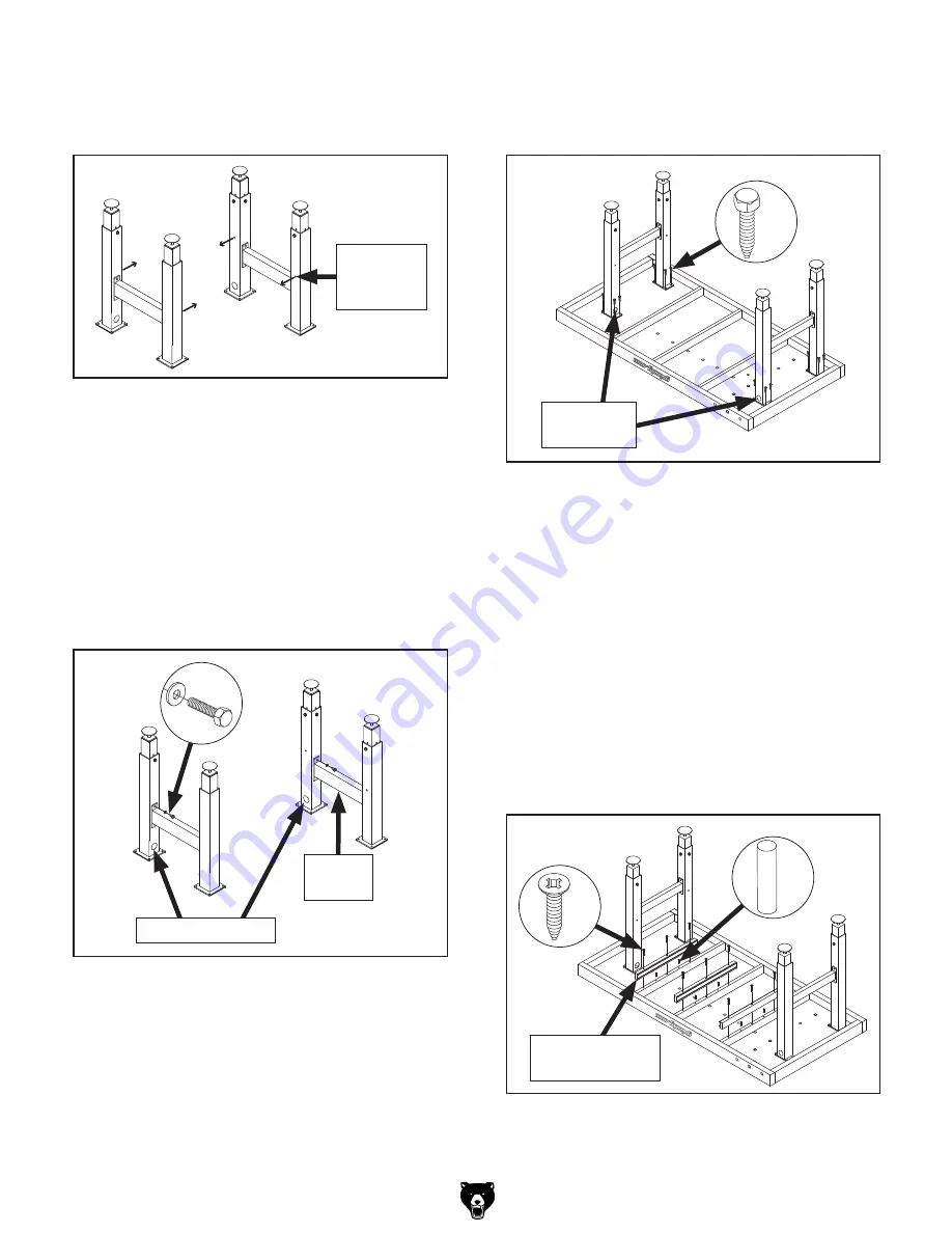
13. Secure leg assemblies to workbench top
with (16)
5
⁄
16
" x 1" lag screws, as shown in
Figure 13.
Figure 13. Leg assemblies installed.
x 16
Leadscrew
Holes
14. Fully tighten all fasteners securing work-
bench top and leg assemblies.
Note:
In next step, make sure that drawer
slides on support assemblies are facing cor-
rect way to accept drawers.
15. Use (6) wood dowels to attach drawer sup-
port assemblies to workbench top, as shown
in
Figure 14.
16. Secure drawer support assemblies to work-
bench top with (9) #10 x 1
1
⁄
2
" wood screws
(see
Figure 14).
Figure 14. Installing drawer support assemblies.
x 6
Drawer Support
Assembly
x 9
Figure 12. Leg assemblies.
Note: In next step, orient legs so bottom shelf
hole in each leg will face inward, as shown in
Figure 11.
x 8
Leg
Support
Leadscrew Holes
Bottom
Shelf Hole
(1 of 4)
Note:
In next step, legs must also be ori-
ented so one leadscrew hole faces to side,
and other faces front (see
Figure 12). This is
necessary to properly install vise assemblies
in later step.
12. Attach leg supports to leg assemblies with
(8)
5
⁄
16
"-18 x
3
⁄
4
" hex bolts and
5
⁄
16
" flat wash-
ers, and hand-tighten fasteners, as shown in
Figure 12.
Figure 11. Bottom shelf holes facing inward.
Note: In next step, take care to properly ori-
ent leadscrew holes in leg assemblies with
holes in workbench top to accept vise lead-
screws in later step (see
Figure 13).


