Model T27338 (Mfd. Since 01/15)
-19
-
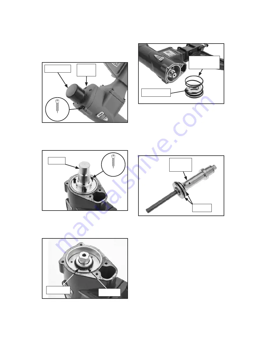
5. Twist off head cap shown in Figure 28.
6. Remove (4) cap screws from cylin-
der cover shown in
Figure 28. Slide
cylinder cover and rubber gasket off
plunger.
Figure 28. Cylinder cover location.
Cylinder
Cover
Head Cap
9. Push driver up to remove plung-
er seat and compression spring
(see
Figure 31).
8. Remove snap ring and split ring from
top of piston assembly (see
Figure 30).
Figure 30. Split ring and snap ring
location.
Split Ring
7. Unscrew (3) cap screws and remove
plunger (see
Figure 29).
Figure 29. Plunger location.
Plunger
10. Grab onto driver and pull piston assem-
bly out from bottom.
11. Apply thin film of nailer lubricating oil on
O-rings of new piston assembly.
12. Re-assemble nailer in reverse order.
Figure 31. Plunger seat and compression
spring.
Figure 32. Piston and driver.
(1 of 4)
(1 of 3)
Snap Ring
Compression
Spring
Plunger Seat
Piston
Assembly
O-Rings
Summary of Contents for T27338
Page 28: ......


