background image

-4-

Model T28192 (Mfd. Since 04/18)

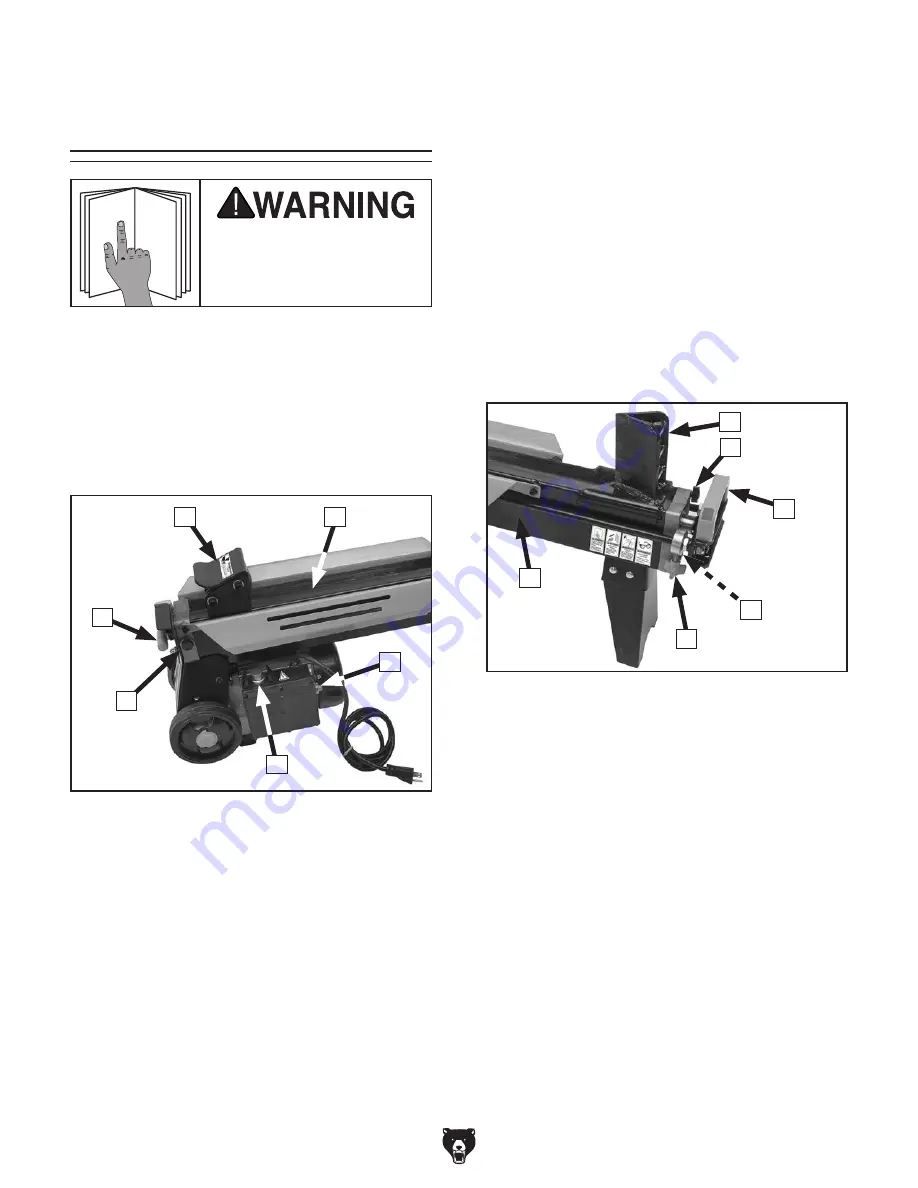
Controls & 

Components

A.   Hydraulic  Ram:  Drives  logs  into  splitting 

wedge. Delivers 6.5 tons of ram force.

B.   Log  Bed:  Supports  logs  during  log  splitting 

operations.

C.  Circuit Breaker Reset Button:  Circuit 

breaker trips if motor draws excessive current 
and overheats. Push to reset circuit breaker 
after allowing machine to cool down.

To reduce your risk of 

serious injury, read this 

entire manual BEFORE 

using machine.

Refer to the following figures and descriptions to 
become familiar with the basic controls and com-
ponents  of  this  machine.  Understanding  these 
items and how they work will help you understand 
the rest of the manual and stay safe when operat-
ing this machine.

Controls & Components

Figure 1. Controls and components—rear. 

G.   Splitting  Wedge:  Stationary  high-carbon 

steel wedge that splits logs.

H.  Air Bleed Screw:  Loosen  screw  slowly  to 

release air inside hydraulic cylinder.

I.  Transport Handle: Allows for easy lifting and 

moving of log splitter.

J.  Hydraulic Fluid Tank Plug w/Dipstick: 

Remove to check fluid level and add/change 
hydraulic fluid. 

K.  Hydraulic Ram Return Stop:  Sets  start 

position for hydraulic ram.

L.  Hydraulic Fluid Tank: Holds  3.7  quarts  of 

ISO 22 or equivalent hydraulic fluid.

F

A

B

E

D

Figure 2. Controls and components—front. 

I

G

H

K

J

L

D.   ON  Button:  When  pushed  and  held, 

starts  and  runs  motor  to  pressurize 
hydraulic  fluid.  ON  button  and  hydraulic 
control lever must be held simultaneously to 
activate hydraulic ram.

E.  Hydraulic Control Valve Pressure Release: 

Slowly  loosen  hex  bolt  to  release  pressure 
inside hydraulic control valve if hydraulic ram 
does not return to start position.

F.  Hydraulic Control Lever: Push  down 

to  activate  hydraulic  ram.  Hydraulic 
control lever and ON button must be pushed 
and held simultaneously to activate hydraulic 
ram.

C

Summary of Contents for T28192

Page 1: ...UAL For models manufactured since 04 18 COPYRIGHT MAY 2018 BY GRIZZLY INDUSTRIAL INC WARNING NO PORTION OF THIS MANUAL MAY BE REPRODUCED IN ANY SHAPE OR FORM WITHOUT THE WRITTEN APPROVAL OF GRIZZLY IN...

Page 2: ...g grinding tool integrity and the usage of personal protective equipment The manufacturer will not be held liable for injury or property damage from negligence improper training machine modifications...

Page 3: ...un 14 SECTION 4 OPERATIONS 15 Operation Overview 15 Using Hydraulic Control Lever 16 Setting Hydraulic Ram Start Position 16 Splitting Logs 16 Removing Stuck Log 17 SECTION 5 ACCESSORIES 18 SECTION 6...

Page 4: ...ade every effort to be exact with the instruc tions specifications drawings and photographs in this manual Sometimes we make mistakes but our policy of continuous improvement also means that sometimes...

Page 5: ...uctions in this manual To reduce your risk of serious injury read this entire manual BEFORE using machine Wheels Power Switch Electric Motor Hydraulic Fluid Tank Hydraulic Ram Return Stop Transport Ha...

Page 6: ...steel wedge that splits logs H Air Bleed Screw Loosen screw slowly to release air inside hydraulic cylinder I Transport Handle Allows for easy lifting and moving of log splitter J Hydraulic Fluid Tank...

Page 7: ...Yes Power Cord Length 6 ft Power Cord Gauge 14 AWG Plug Included Yes Included Plug Type 5 15 Switch Type Push Button Motors Main Horsepower 1 75 HP Phase Single Phase Amps 15A Speed 3450 RPM Type TEF...

Page 8: ...ear Serial Number Location ID Label ISO 9001 Factory Yes Certified by a Nationally Recognized Testing Laboratory No Assembly Time 15 Minutes Features Automatic Cylinder Return 20 L x 10 D Log Capacity...

Page 9: ...proof DANGEROUS ENVIRONMENTS Do not use machinery in areas that are wet cluttered or have poor lighting Operating machinery in these areas greatly increases the risk of accidents and injury MENTAL ALE...

Page 10: ...moving parts or flying debris Make sure they are properly installed undamaged and working correctly BEFORE operating machine FORCING MACHINERY Do not force machine It will do the job safer and better...

Page 11: ...ost invisible to the naked eye SUPPORTING LOGS Never use hands or any part of your body to support a log when activat ing hydraulic ram Avoid getting hands or fingers caught between logs and hydraulic...

Page 12: ...circuit To reduce the risk of these hazards avoid over loading the machine during operation and make sure it is connected to a power supply circuit that meets the specified circuit requirements For yo...

Page 13: ...outlets do not meet the grounding requirements for this machine Do not modify or use an adapter on the plug provided if it will not fit the outlet have a qualified electrician install the proper outl...

Page 14: ...machine and have resolved any issues between Grizzly or the shipping agent You MUST have the original pack aging to file a freight claim It is also extremely helpful if you need to return your machine...

Page 15: ...ting Moving The wheels on the Model T28192 make it possible for one person to move the log splitter short distances however we suggest that you get assistance whenever lifting it Assembly The Model T2...

Page 16: ...e until it stops then turn it counterclockwise two full turns 5 Press and hold ON button then push hydraulic control lever down Hydraulic ram should move forward stopping about 8 from splitting wedge...

Page 17: ...how to books trade magazines or websites To complete a typical operation the operator does the following 1 DISCONNECTS MACHINE FROM POWER 2 Checks that hydraulic tank is filled with proper amount of...

Page 18: ...sense to set the start position of the ram closer to the splitting wedge Doing so will reduce the time it takes you to complete your operation To set hydraulic ram start position 1 Turn air bleed scre...

Page 19: ...Removing Stuck Log Occasionally logs will not split and become stuck on the splitting wedge When this happens DO NOT try to remove it by hand or by kicking it This can result in personal injury and da...

Page 20: ...in a variety of working conditions Figure 10 Assortment of gloves T21272 T21273 T20692 Figure 11 T23381 Large Disposable Black Nitrile Gloves T23381 KincoTM Disposable Black Nitrile Gloves Large 40 Pk...

Page 21: ...tor Steering handle is padded for comfort Platform size is 48 x 24 Maximum capacity 700 lbs Figure 16 T27503 Large Wood Grip T27503 Wood Grip Large This wood handle fits 10 files to give them a more e...

Page 22: ...ing operations Low hydraulic fluid level Dry hydraulic ram Leaking hydraulic fluid Loose hardware Any other unsafe or abnormal condition Every 150 Hours of Use Change hydraulic fluid Schedule To reduc...

Page 23: ...Figure 18 Log splitter positioned for fluid check Wood Block Hydraulic Fluid Tank Plug Figure 19 Proper hydraulic fluid level on dipstick Proper Hydraulic Oil Level Low Mark High Mark 5 Re install plu...

Page 24: ...points Figure 20 Removing plug to drain hydraulic fluid Plug Drain Pan To change hydraulic fluid 1 DISCONNECT MACHINE FROM POWER 2 Put on safety glasses and latex gloves 3 Place drain pan under hydrau...

Page 25: ...d or corroded wires 5 Replace ON button 6 Test replace if at fault 7 Test repair replace Machine stalls or is underpowered 1 Log exceeds splitter capacity 2 Log improperly positioned on bed or attempt...

Page 26: ...Replace ram assembly and flush service hydraulic system Page 22 Hydraulic ram retracts slowly or not at all but moves forward correctly 1 Hydraulic control lever at fault 2 Hydraulic control valve at...

Page 27: ...napproved after market parts WIRE CONNECTIONS All connections must be tight to prevent wires from loosening during machine operation Double check all wires dis connected or connected during any wiring...

Page 28: ...ON PAGE 25 Wiring Diagram Kedu HY56 Kuoyuh 20A Hot Ground Neutral Start Capacitor 80uF 300VAC 110 VAC 5 15 Plug 125 250VAC 88 Series GND ON OFF SWITCH CIRCUIT BREAKER Bottom of Switch Electrical Comp...

Page 29: ...43 44 45 46 47 48 49 50 51 52 53 54 55 57 58 60 61 62 63 64 65 66 67 68 69 70 71 72 73 74 75 76 77 78 79 80 81 82 83 84 85 86 88 90 91 92 93 94 95 96 97 98 99 100 101 102 103 104 105 106 116 117 118 1...

Page 30: ...92026 O RING 7 X 1 9 82 PT28192082 PHLP HD SCR M5 8 X 10 27 PT28192027 KNOB BOLT M5 8 X 12 30D WING 83 PT28192083 LEG 28 PT28192028 FLAT WASHER 14MM 84 PT28192084 HEX NUT M8 1 25 29 PT28192029 CAP SCR...

Page 31: ...0 523 4777 or www grizzly com Labels Cosmetics 201 202 203 204 205 206 207 208 209 210 211 REF PART DESCRIPTION REF PART DESCRIPTION 201 PT28192201 TOUCH UP PAINT ORANGE 207 PT28192207 READ MANUAL WAR...

Page 32: ...by moving control lever back and fourth a few times Ignoring this warning can lead to hydraulic fluid penetrating your skin and entering your bloodstream This blood poisoning could result in an agress...

Page 33: ...metalworker ____ 0 2 Years ____ 2 8 Years ____ 8 20 Years ____20 Years 6 How many of your machines or tools are Grizzly ____ 0 2 ____ 3 5 ____ 6 9 ____10 7 Do you think your machine represents a good...

Page 34: ...LINE FOLD ALONG DOTTED LINE GRIZZLY INDUSTRIAL INC P O BOX 2069 BELLINGHAM WA 98227 2069 Place Stamp Here Name_______________________________ Street_______________________________ City______________S...

Page 35: ...shall be tried in the State of Washington County of Whatcom We shall in no event be liable for death injuries to persons or property or for incidental contingent special or consequential damages arisi...

Page 36: ......

Reviews: