background image

WARRANTY AND RETURNS

Grizzly Industrial, Inc. warrants every product it sells for a period of 

1 year to the original purchaser from 

the date of purchase. This warranty does not apply to defects due directly or indirectly to misuse, abuse, 
negligence, accidents, repairs or alterations or lack of maintenance. This is Grizzly’s sole written warranty 
and any and all warranties that may be implied by law, including any merchantability or fitness, for any par-
ticular purpose, are hereby limited to the duration of this written warranty. We do not warrant or represent 
that the merchandise complies with the provisions of any law or acts unless the manufacturer so warrants. 
In no event shall Grizzly’s liability under this warranty exceed the purchase price paid for the product and 
any legal actions brought against Grizzly shall be tried in the State of Washington, County of Whatcom.

We shall in no event be liable for death, injuries to persons or property or for incidental, contingent, special, 
or consequential damages arising from the use of our products.

To take advantage of this warranty, contact us by mail or phone and give us all the details. We will then 
issue you a “Return Number,’’ which must be clearly posted on the outside as well as the inside of the 
carton.  We  will  not  accept  any  item  back  without  this  number.  Proof  of  purchase  must  accompany  the 
merchandise. 

The manufacturers reserve the right to change specifications at any time because they constantly strive to 
achieve better quality equipment. We make every effort to ensure that our products meet high quality and 
durability standards and we hope you never need to use this warranty.

Please feel free to write or call us if you have any questions about the machine or the manual. 

Thank you again for your business and continued support. We hope to serve you again soon.

WARRANTY AND RETURNS

Summary of Contents for T28366

Page 1: ...ufactured since 04 18 COPYRIGHT MAY 2018 BY GRIZZLY INDUSTRIAL INC WARNING NO PORTION OF THIS MANUAL MAY BE REPRODUCED IN ANY SHAPE OR FORM WITHOUT THE WRITTEN APPROVAL OF GRIZZLY INDUSTRIAL INC ESAB1...

Page 2: ...g grinding tool integrity and the usage of personal protective equipment The manufacturer will not be held liable for injury or property damage from negligence improper training machine modifications...

Page 3: ...ERATIONS 19 Operation Overview 19 Using Coolant System 20 Selecting Blades 21 Breaking In Blades 23 Controlling Feed Rate 23 Installing Changing Blades 24 Evaluating Cutting Performance 26 Adjusting V...

Page 4: ...ade every effort to be exact with the instruc tions specifications drawings and photographs in this manual Sometimes we make mistakes but our policy of continuous improvement also means that sometimes...

Page 5: ...ead this entire manual BEFORE using machine Coolant Hose Miter Angle Gauge Vise Coolant Flow Control Valve Blade Guards Miter Lock Lever Vise Handwheel Splash Guard Vise Depth Stop Oil Level Sight Gla...

Page 6: ...r to motor and remains depressed until reset Twist clockwise to reset D Master Power Switch Supplies power to machine for operation E Depth Stop Stops blade at specific depth to produce multiple same...

Page 7: ...l Power Requirement 115V Single Phase 60 Hz Full Load Current Rating 8 5A Minimum Circuit Size 15A Connection Type Cord Plug Power Cord Included Yes Power Cord Length 6 ft Power Cord Gauge 14 AWG Plug...

Page 8: ...w Wheel Guard Steel Body Construction Cast Iron Paint Enamel Other Specifications Country of Origin China Warranty 1 Year Approximate Assembly Setup Time 1 Hour Serial Number Location Machine ID Label...

Page 9: ...roof DANGEROUS ENVIRONMENTS Do not use machinery in areas that are wet cluttered or have poor lighting Operating machinery in these areas greatly increases the risk of accidents and injury MENTAL ALER...

Page 10: ...moving parts or flying debris Make sure they are properly installed undamaged and working correctly BEFORE operating machine FORCING MACHINERY Do not force machine It will do the job safer and better...

Page 11: ...ine components ejections of hot chips swarf and the workpiece itself can cause burns HAND PLACEMENT Never position fingers or thumbs in line with the cut Hands could be crushed in vise or from falling...

Page 12: ...ially if connected to an undersized circuit To reduce the risk of these hazards avoid over loading the machine during operation and make sure it is connected to a power supply circuit that meets the s...

Page 13: ...ler sizes Any extension cord used with this machine must be in good condition and contain a ground wire and matching plug receptacle Additionally it must meet the following size requirements Minimum G...

Page 14: ...fting Straps Rated Min 250 lbs 2 Flat Head Screwdriver 2 1 Adjustable Wrench 1 Open End Wrench 12mm 1 Hex Wrench 8mm 1 Hex Wrench 5mm 1 Retaining Ring Pliers 1 T28368 Cold Saw Blade Not Included 1 SEC...

Page 15: ...entilated area to minimize exposure to toxic fumes Before cleaning gather the following Disposable rags Cleaner degreaser WD 40 works well Safety glasses disposable gloves Plastic paint scraper option...

Page 16: ...ry when establishing a location for this machine in the shop Below is the minimum amount of space needed for the machine Placement Location Site Considerations Figure 7 Minimum working clearances 181...

Page 17: ...ing instructions included with Model T28367 Bench Mounting Figure 12 Direct Mount setup Machine Base Workbench Lag Screw Flat Washer Another option is a direct mount see example below where the machin...

Page 18: ...glass refer to Gearbox Oil on Page 32 If oil level is at least halfway up sight glass no further action is required Continue to Step 6 Figure 16 Location of oil sight glass Figure 15 Lever arm and tr...

Page 19: ...ury or death can result from using this machine BEFORE understanding its controls and related safety information DO NOT operate or allow others to operate machine until the information is understood 7...

Page 20: ...button Saw should NOT start If saw does start turn off master power switch and immediately disconnect power to saw The Emergency Stop button may not be working properly The safety feature must work pr...

Page 21: ...ith a basic understanding of how the machine is used during operation so the machine controls components discussed later in this manual are easier to understand Due to the generic nature of this overv...

Page 22: ...ack into the reservoir through the tray screen where the swarf and metal chips are filtered out To use coolant system 1 Add coolant to coolant reservoir refer to Coolant System on Page 30 for instruct...

Page 23: ...e Blade Pitch The most important consideration when selecting a blade for the Model T28366 is blade pitch which is typically measured in teeth per inch TPI Proper TPI for any cut depends on the cross...

Page 24: ...art Similarly if the workpiece is a soft metal such as aluminum each tooth will remove more material and rapidly fill the blade gullet For this reason use a blade with fewer TPI on soft metals An addi...

Page 25: ...Height L Length D Diameter Th Material Thickness 3 14 A D x x Th A 2H 2L x Th Figure 29 Calculating cut area for break in Controlling Feed Rate Blade feed rate refers to the period of time it takes t...

Page 26: ...cked regularly for wear or damage to help ensure operator safety and high quality cutting results Always immediately replace any blade found with damage Item s Needed Qty New 10 Cold Cut Saw Blade 1 H...

Page 27: ...ard linkage 5 Rotate retractable blade guards out of way and remove blade flange and blade see Figure 33 Note Blade flange and blade need to be moved slightly to the left to clear pins on blade arbor...

Page 28: ...hin straight powdery thin curled tightly hard thin thin curled short hard thick thick hard strong thick hard strong thin straight powdery thin curled tightly hard thin thin curled short hard thick thi...

Page 29: ...contacts jaws perform Steps 4 8 5 Slide jaws away from blade then lower blade and position each jaw approximately 1 2 away from blade see Figure 37 Note At certain angle settings it may not be possibl...

Page 30: ...scale Miter Scale Miter Lock Lever Prior to cutting always check vise jaws for blade clearance Failure to do this could cause blade to contact vise during cut resulting in damage to blade or jaws To s...

Page 31: ...accessories H9240 RustlickTM WS5050 Heavy Duty Soluble Oil 1 Gal Effective general purpose and heavy duty chlorinated E P additive provides excellent tool life and helps protect neoprene seals Can be...

Page 32: ...age 33 Lubricate saw base pivot see Page 33 Every Six Months Change gearbox oil see Page 32 Schedule Cleaning Protecting Metal chips left on the machine that have been soaked with water based coolant...

Page 33: ...NNECT MACHINE FROM POWER 2 Wearing protective equipment open coolant reservoir lid see Figure 43 3 Remove and wipe coolant pump clean see Figure 43 4 Siphon and dispose of old coolant and swarf accord...

Page 34: ...away any excess oil and re install lever arm Figure 45 Oil fill and drain plug locations Sight Glass Lubrication This cold cut saw requires regular lubrication to maintain smooth movement and ensure l...

Page 35: ...ment of the saw headstock If saw headstock movement becomes difficult apply a small amount of oil to column joints see Figure 47 Move the saw headstock back and forth several times to distribute oil e...

Page 36: ...switch 9 Test repair replace Machine stalls or is under powered 1 Dull blade 2 Workpiece crooked vise jaws are loose or incorrectly adjusted 3 Not enough coolant flowing onto workpiece 4 Machine unde...

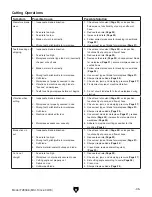
Page 37: ...pressure Page 27 8 Find correct source of machine vibration 9 Do not allow blade teeth to touch workpiece during start up Vibration when cutting 1 Inadequate blade lubrication 2 Workpiece not properly...

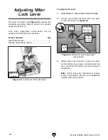
Page 38: ...t or right as need ed Re tighten cap screws and tensioner hex nuts and then test miter lock lever range of movement Note Check lock lever clearance to ensure it does not interfere with the vise handwh...

Page 39: ...t at the time of printing but may not match your machine If you find this to be the case use the wiring diagram inside the motor junction box CAPACITORS INVERTERS Some capacitors and power inverters s...

Page 40: ...4 18 READ ELECTRICAL SAFETY ON PAGE 37 Electrical Components Figure 51 Power switch Figure 54 Emergency Stop and On button Figure 52 Connector Figure 55 Transformer Figure 56 Coolant pump motor Figure...

Page 41: ...R BUTTON MASTER POWER SWITCH TRANSFORMER Run Capacitor 65uF 250V Start Capacitor 500uF 125V POWER 20VA TC Neutral Hot Ground 110 VAC 5 15 Plug Pump Motor SongLong SL 401 120V 15W 760 L H Cansen LW30 2...

Page 42: ...0 12 1 8 14 15 16 34 17 18 19 20 21 22 23 24 25 26 27 28 29 30 31 32 9 38 14 1 14 2 14 3 14 4 22 1 14 5 14 6 Motor SECTION 9 PARTS We do our best to stock replacement parts when possible but we cannot...

Page 43: ...SCREW M6 1 X 20 25 PT28366025 FLAT WASHER 6MM 10 PT28366010 MOTOR MOUNT 26 PT28366026 LOCK WASHER 6MM 11 PT28366011 EXT RETAINING RING 14MM 27 PT28366027 OIL SIGHT GLASS 12 PT28366012 KEY 5 X 5 X 10 2...

Page 44: ...50 PT28366050 LOCK COLLAR 82 PT28366082 CAP SCREW M8 1 25 X 60 51 PT28366051 RETAINING PIN 83 PT28366083 HEX NUT M8 1 25 52 PT28366052 HINGE PIN 84 PT28366084 SPRING ARM UPPER 53 PT28366053 RETAINING...

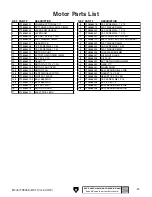
Page 45: ...66111 RIVET 2 X 6MM 136 PT28366136 MITER BASE 112 PT28366112 SPLASH GUARD SUPPORT 137 PT28366137 SPACER 26 ID X 60 OD 113 PT28366113 CAP SCREW M6 1 X 16 138 PT28366138 STUD UDE M20 2 5 114 PT28366114...

Page 46: ...8366158 STRAIN RELIEF TYPE 3 M16 1 5 153 PT28366153 TRANSFORMER 115V AC IP 24V AC OP 159 PT28366159 POWER CORD 3W 14G 72 5 15P 154 PT28366154 ROTARY SWITCH CANSEN LW30 20 160 PT28366160 STRAIN RELIEF...

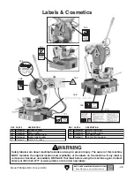
Page 47: ...NG Mfd for Grizzly in China Date S N 1 Read and understand owner s manual before operating 2 Always wear approved safety glasses AND face shield 3 Only plug power cord into a grounded outlet 4 Disconn...

Page 48: ......

Page 49: ...metalworker ____ 0 2 Years ____ 2 8 Years ____ 8 20 Years ____20 Years 6 How many of your machines or tools are Grizzly ____ 0 2 ____ 3 5 ____ 6 9 ____10 7 Do you think your machine represents a good...

Page 50: ...LINE FOLD ALONG DOTTED LINE GRIZZLY INDUSTRIAL INC P O BOX 2069 BELLINGHAM WA 98227 2069 Place Stamp Here Name_______________________________ Street_______________________________ City______________S...

Page 51: ...tried in the State of Washington County of Whatcom We shall in no event be liable for death injuries to persons or property or for incidental contingent special or consequential damages arising from...

Page 52: ......

Reviews: