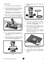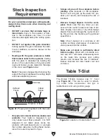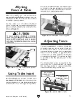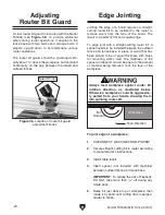
-12-
Model T31636 (Mfd. Since 02/20)
Site Considerations
Figure 5. Minimum working clearances.
27"
16"
Dust Port
Children and visitors may be
seriously injured if unsuper-
vised around this machine.
Lock entrances to the shop
or disable start switch or
power connection to prevent
unsupervised use.
Workbench Load
Refer to the
Machine Data Sheet for the weight
and footprint specifications of your machine.
Some workbenches may require additional rein-
forcement to support the weight of the machine
and workpiece materials.
Consider anticipated workpiece sizes and addi-
tional space needed for auxiliary stands, work
tables, or other machinery when establishing a
location for this machine in the shop. Below is
the minimum amount of space needed for the
machine.
Placement Location
Assembly
To assemble router table:
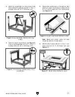
1. Attach two legs together with (1) lower short
brace at bottom using (4)
5
⁄
16
"-18 x
1
⁄
2
"
carriage
bolts and (4)
5
⁄
16
"-18 flange nuts (see
Figure
6). Repeat with second pair of legs and (1)
lower short brace.
The machine must be fully assembled before it
can be operated. Before beginning the assembly
process, refer to
Needed for Setup and gather
all listed items. To ensure the assembly process
goes smoothly, first clean any parts that are cov-
ered or coated in heavy-duty rust preventative (if
applicable).
Figure 6. Legs assembled.
Legs
Brace
Feet
x 4
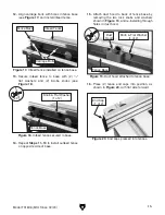
2. Install (1) adjustable foot in bottom of each
leg with (1)
3
⁄
8
" flat washer and (1)
3
⁄
8
"-16 hex
nut each (see
Figure 7).
Figure 7. Feet installed in bottom of legs.
x 4
Summary of Contents for T31636
Page 36: ......


