background image

-18-

Model T32002 (Mfd. Since 02/20)

Assembly

To assemble machine:

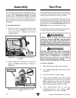
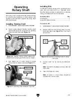
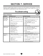
1.  Attach  tool  rest  to  mounting  bracket  using 

M6-1 x 13  knob (see 

Figure 9). There should 

be  no  more  than 

1

8

"  between  tool  rest  and 

grinding wheel.

The  machine  must  be  fully  assembled  before  it 
can be operated. Before beginning the assembly 
process,  refer  to 

Needed for Setup  and  gather 

all listed items. To ensure the assembly process 
goes smoothly, first clean any parts that are cov-
ered or coated in heavy-duty rust preventative (if 
applicable).

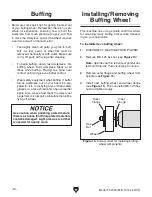
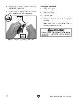
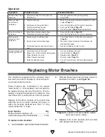
2.  Attach safety shield to wheel cover using (2) 

M4-.7 x 5 Phillips head screws, as shown in 

Figure 10.

Knob

Figure 9. Tool rest attached to mounting 

bracket.

Tool Rest

Figure 10. Safety shield attached to wheel 

cover.

Safety Shield

x 2

Wheel Cover

Test Run

Once assembly is complete, test run the machine 
to  ensure  it  is  properly  connected  to  power  and 
safety components are functioning correctly.

If you find an unusual problem during the test run, 
immediately stop the machine, disconnect it from 
power, and fix the problem BEFORE operating the 
machine again. The 

Troubleshooting table in the 

SERVICE section of this manual can help.

DO NOT start machine until all preceding 

setup instructions have been performed. 

Operating an improperly set up machine 

may result in malfunction or unexpect-

ed results that can lead to serious injury, 

death, or machine/property damage.

Serious injury or death can result from 

using this machine BEFORE understanding 

its controls and related safety information. 

DO NOT operate, or allow others to operate, 

machine until the information is understood. 

To test run machine:

1.  Clear all setup tools away from machine.

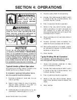
2.  Turn variable-speed dial all the way counter-

clockwise.

3.  Connect machine to power supply.

4.  Verify  motor  operation  by  slowly  turning 

variable-speed dial clockwise to turn machine 

ON. Rotate dial back and forth to test variable-
speed  function.  Motor  should  run  smoothly 
and without unusual problems or noises.

5.  Turn  variable-speed  dial  all  the  way 

counterclockwise  to  turn  machine 

OFF

Congratulations! Test run is complete.

The Test Run consists of verifying the following: 1) 
The motor powers up and runs correctly.

Mounting Bracket

Summary of Contents for T32002

Page 1: ...O PORTION OF THIS MANUAL MAY BE REPRODUCED IN ANY SHAPE OR FORM WITHOUT THE WRITTEN APPROVAL OF GRIZZLY INDUSTRIAL INC CS20950 PRINTED IN CHINA V1 03 20 MODEL T32002 3 VS MINI GRINDER BUFFER w ROTARY...

Page 2: ...g grinding tool integrity and the usage of personal protective equipment The manufacturer will not be held liable for injury or property damage from negligence improper training machine modifications...

Page 3: ...n 18 SECTION 4 OPERATIONS 19 Workpiece Inspection 20 Selecting Grinding Wheel 20 Caring for Grinding Wheel 21 Inspecting Grinding Wheel 21 Dressing Grinding Wheel 22 Storing Grinding Wheel 22 Installi...

Page 4: ...ade every effort to be exact with the instruc tions specifications drawings and photographs in this manual Sometimes we make mistakes but our policy of continuous improvement also means that sometimes...

Page 5: ...wn below to better understand the instructions in this manual Tool Rest Grinding Wheel Rotary Shaft Wheel Cover Safety Shield Grinding Bit Variable Speed ON OFF Switch Buffing Wheel For Your Own Safet...

Page 6: ...C Grinding Wheel Spins to grind workpiece Can be replaced with different grit wheels for different operations D Tool Rest Provides flat surface to rest workpiece on during operations Figure 3 Grindin...

Page 7: ...ment 110V Single Phase 60 Hz Full Load Current Rating 1 5A Minimum Circuit Size 15A Connection Type Cord Plug Power Cord Included Yes Power Cord Length 6 ft Power Cord Gauge 18 AWG Plug Included Yes I...

Page 8: ...1 1 8 in Work Rest Length 1 3 4 in Work Rest Thickness 1 16 in Construction Base Cast Iron Work Rest Steel Eye Shields Clear Plastic Paint Finish Enamel Other Specifications Country of Origin China W...

Page 9: ...d proof DANGEROUS ENVIRONMENTS Do not use machinery in areas that are wet cluttered or have poor lighting Operating machinery in these areas greatly increases the risk of accidents and injury MENTAL A...

Page 10: ...moving parts or flying debris Make sure they are properly installed undamaged and working correctly BEFORE operating machine FORCING MACHINERY Do not force machine It will do the job safer and better...

Page 11: ...ick back Always grind on downward part of wheel WHEEL ATTACHMENT Only use flanges includ ed with grinder when mounting wheels Other flanges may not properly secure wheel and cause an accident Do not u...

Page 12: ...place DO NOT wear loose clothing gloves or jewelry and tie back long hair EYE FACE LUNG PROTECTION Always wear eye protection or face shield and heavy leather apron when operating buffer Wear dust mas...

Page 13: ...p before starting rotary tool Jamming tool against workpiece could cause workpiece or tool to shatter and send debris in all directions Firmly grasp rotary tool and ease it into workpiece Entanglement...

Page 14: ...rsized circuit To reduce the risk of these hazards avoid over loading the machine during operation and make sure it is connected to a power supply circuit that meets the specified circuit requirements...

Page 15: ...ord size gets longer and the gauge size gets smaller higher gauge numbers indicate smaller sizes Any extension cord used with this machine must be in good condition and contain a ground wire and match...

Page 16: ...file a freight claim It is also extremely helpful if you need to return your machine later Unpacking The following items are needed but not included for the setup assembly of this machine NOTICE If yo...

Page 17: ...e in the shop Below is the minimum amount of space needed for the machine Placement Location Bench Mounting Figure 8 Direct Mount setup Machine Base Workbench Lag Screw Flat Washer Another option is a...

Page 18: ...t it from power and fix the problem BEFORE operating the machine again The Troubleshooting table in the SERVICE section of this manual can help DO NOT start machine until all preceding setup instructi...

Page 19: ...safe grinding 5 Ensures that variable speed ON OFF switch is turned all the way counterclockwise and connects machine to power 6 Puts on personal protective equipment 7 Stands to the side starts machi...

Page 20: ...kpiece is strong enough to be ground Should it break the broken piece may dig into the wheel and cause kickback or severe injury Selecting Grinding Wheel The Model T32002 only accepts Type 1 wheels wi...

Page 21: ...Oxide 60 Grit Grade L Vitrified Bond 3 At spots shown in Figure 11 gently tap grind ing wheel with a light non metallic device such as handle of a screwdriver or a wooden mallet Note Finding exact sp...

Page 22: ...everal different types of wheel dressing devices available on the market see Accessories on Page 27 for examples Dressing restores the abrasive quality of the wheel surface and brings the wheel edge b...

Page 23: ...used If wheel appears to wobble grinder vibrates excessively or any other unsafe condition appears with new wheel stop grinder and refer to Troubleshooting on Page 29 Warped wheel flanges can contrib...

Page 24: ...e flying at you Wear safety glasses or a face shield and a heavy leather apron Also wear a dust mask to protect your lungs from microscopic particulate that will be flying off wheel Use caution when p...

Page 25: ...standoff stud wheel guard removed for clarity Flexible Rotating Shaft Standoff Stud Rotary Shaft The Model T32002 comes with a grinding bit and uses bits and cutters with a 1 8 diameter shaft See the...

Page 26: ...iece of material similar to workpiece Using Rotary Shaft 5 Hand tighten collet nut while pin wrench is inserted into locking hole Failure to wear safety glasses while operat ing grinder could cause se...

Page 27: ...s are hardened steel Cast iron handle provides stabilizing mass for better control Figure 20 Rotary type dressing tools H5891 1 2 Carat Diamond Dresser H5892 3 4 Carat Diamond Dresser Industrial diamo...

Page 28: ...ly easy Vacuum excess debris and wipe off the remain ing dust with a dry cloth Cleaning Protecting The grinding wheel should be inspected before every use Use the ring test method noted in Inspecting...

Page 29: ...orroded connections Page 31 4 Remove replace brushes Page 30 5 Replace 6 Replace 7 Test repair replace Machine stalls or is underpowered 1 Machine undersized for task 2 Motor brushes at fault 3 Motor...

Page 30: ...s quickly grit falls off 1 Workpiece pressure too great 2 Wheel is too soft for material being ground 3 Wheel diameter too small 4 Wheel dressed incorrectly 5 Defective wheel bonding 1 Use less workpi...

Page 31: ...rrent at the time of printing but may not match your machine If you find this to be the case use the wiring diagram inside the motor junction box CAPACITORS INVERTERS Some capacitors and power inverte...

Page 32: ...nce 02 20 READ ELECTRICAL SAFETY ON PAGE 31 Neutral Hot Ground 110 VAC 5 15 Plug MOTOR 110V Circuit Board N A P o t e ntiom e t e r BASE Wiring Diagram Figure 24 Motor wiring and switch Figure 25 Wiri...

Page 33: ...STATOR CLAMP 5 PT32002005 BALL BEARING 6200ZZ 21 PT32002021 SPACER 4 4 X 8 1 X 15 6 PT32002006 EXT RETAINING RING 10MM 22 PT32002022 BRUSH HOLDER 7 PT32002007 ROTOR 23 PT32002023 SPACER 4 4 X 8 1 X 8...

Page 34: ...LOCK WASHER 5MM 40 PT32002040 COMPRESSION SPRING 1 X 13 X 95 56 PT32002056 RUBBER FOOT 41 PT32002041 ROTARY SHAFT BODY 57 PT32002057 PHLP HD SCR M4 7 X 6 42 PT32002042 BALL BEARING 686ZZ 58 PT32002058...

Page 35: ...for incidental contingent special or consequential damages arising from the use of our products The manufacturers reserve the right to change specifications at any time because they constantly strive...

Page 36: ......

Reviews: