background image

-20-

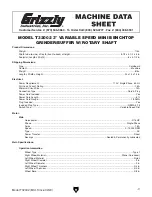
Model T32002 (Mfd. Since 02/20)

Workpiece 

Inspection

Electrical system is not waterproof. DO NOT 

use this grinder with a liquid cooling system 

required for wet grinding wheel operations. 

Ignoring this warning can lead to electrocu-

tion or machine damage.

Some workpieces are not suitable for grinding on 
a  bench  grinder. 

Before  grinding,  inspect all 

workpieces for the following:

• 

Hard Workpiece: Workpieces that are made 
of  stone,  carbide,  stainless  steel,  ceramics, 
glass, or have hardened welds will wear out 
most general-grade grinding wheels quickly. 
If hard materials are to be ground, you must 
install the correct type of grinding wheel.

• 

Soft Workpiece: Workpieces that are made 
of  aluminum,  brass,  lead,  and  other  nonfer-
rous metals will load up in the grinding wheel 
and  render  the  abrasive  useless.  Grinding 
wood,  plastics,  rubber,  fiberglass,  or  other 
soft  materials  can  also  cause  the  same 
problem  and  lead  to  the  wheel  overheating 
and  possibly  bursting  during  use  if  ignored. 
To  restore  a  loaded  grinding  wheel  surface, 
redress with a dressing tool.

• 

Flexible/Unstable Workpiece:  Grinding  on 
the side or the ends of cable, chain, or round 
workpieces creates the hazard of workpiece 
twist  or  grab,  leading  to  entanglement  with 
the  wheel  or  shaft.  This  hazard  must  be 
avoided.

• 

Loose Parts: Make sure that the workpiece 
is  free  of  any  parts  like  springs,  pins,  balls, 
or other components that may loosen or dis-
lodge during grinding, and hit the operator. 

• 

Strength:  Make  sure  that  the  workpiece  is 
strong enough to be ground. Should it break, 
the broken piece may dig into the wheel and 
cause kickback or severe injury.
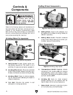
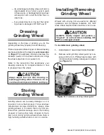
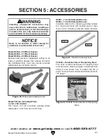
Selecting 

Grinding Wheel

The  Model  T32002  only  accepts  Type  1  wheels 
with a 

3

8

" bore.

Aluminum  oxide  and  silicon  carbide  wheels  are 
marked  in  a  somewhat  uniform  manner  by  all 
the  major  manufacturers.  Understanding  these 
markings will help you understand the capabilities 
of  various  wheels.  Always  refer  to  the  manufac-
turer’s grinding recommendations when selecting 
a wheel for your project.

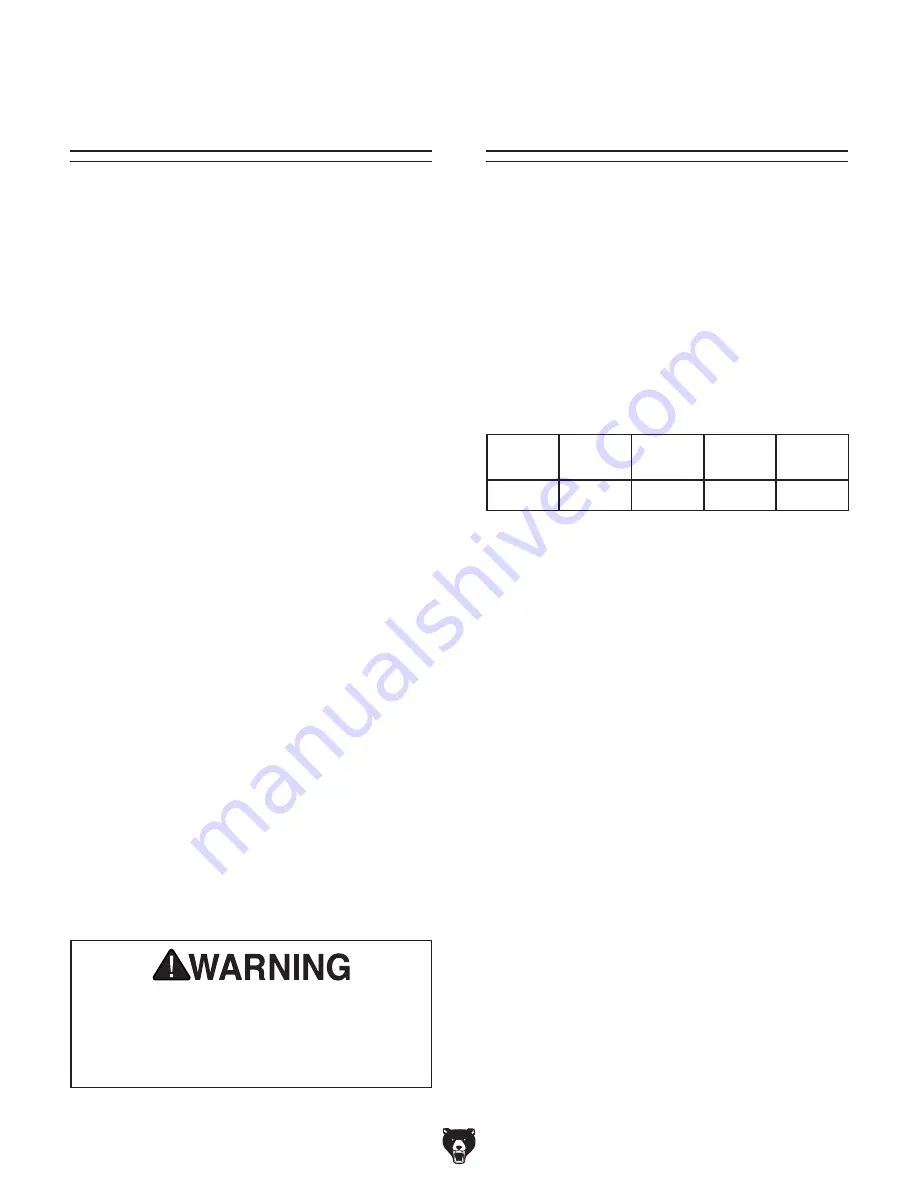
The basic format for wheel numbering is:

Prefix

Abrasive

Type

Grit Size Grade

Bond 

Type

1

A

60

L

V

The 

Prefix is the manufacturer’s designation for a 

particular wheel type (eg. Type 1 wheels).

The  most  common 

Abrasive Types  used  are  A 

for  Aluminum  Oxide,  C  for  Silicon  Carbide,  and 
occasionally SG for Seeded Gel.

The 

Grit Size is a number that refers to the size 

of the abrasive grain in the wheel. The lower the 
number,  the  coarser  the  wheel.  Ten  is  a  very 
coarse wheel for roughing and 220 is usually the 
upper range for fine finish work.

Grade  is  an  indication  of  the  hardness  of  the 
wheel—“A”  being  the  softest  and  “Z”  being  the 
hardest.

Bond Type refers to the type of bonding material 
used to hold the abrasive material. Most general 
purpose wheels will have a “V” indicating Vitrified 
Clay is used. Vitrified Clay provides high strength 
and good porosity. The other common bond type 
is  “B”  for  resin  where  synthetic  resins  are  used. 
These  are  used  to  grind  cemented  carbide  and 
ceramic materials.

Note: There may be other numbers inserted that 
have meaning for a particular type of wheel. Refer 
to the manufacturer’s technical data for a com-
plete explanation.

Summary of Contents for T32002

Page 1: ...O PORTION OF THIS MANUAL MAY BE REPRODUCED IN ANY SHAPE OR FORM WITHOUT THE WRITTEN APPROVAL OF GRIZZLY INDUSTRIAL INC CS20950 PRINTED IN CHINA V1 03 20 MODEL T32002 3 VS MINI GRINDER BUFFER w ROTARY...

Page 2: ...g grinding tool integrity and the usage of personal protective equipment The manufacturer will not be held liable for injury or property damage from negligence improper training machine modifications...

Page 3: ...n 18 SECTION 4 OPERATIONS 19 Workpiece Inspection 20 Selecting Grinding Wheel 20 Caring for Grinding Wheel 21 Inspecting Grinding Wheel 21 Dressing Grinding Wheel 22 Storing Grinding Wheel 22 Installi...

Page 4: ...ade every effort to be exact with the instruc tions specifications drawings and photographs in this manual Sometimes we make mistakes but our policy of continuous improvement also means that sometimes...

Page 5: ...wn below to better understand the instructions in this manual Tool Rest Grinding Wheel Rotary Shaft Wheel Cover Safety Shield Grinding Bit Variable Speed ON OFF Switch Buffing Wheel For Your Own Safet...

Page 6: ...C Grinding Wheel Spins to grind workpiece Can be replaced with different grit wheels for different operations D Tool Rest Provides flat surface to rest workpiece on during operations Figure 3 Grindin...

Page 7: ...ment 110V Single Phase 60 Hz Full Load Current Rating 1 5A Minimum Circuit Size 15A Connection Type Cord Plug Power Cord Included Yes Power Cord Length 6 ft Power Cord Gauge 18 AWG Plug Included Yes I...

Page 8: ...1 1 8 in Work Rest Length 1 3 4 in Work Rest Thickness 1 16 in Construction Base Cast Iron Work Rest Steel Eye Shields Clear Plastic Paint Finish Enamel Other Specifications Country of Origin China W...

Page 9: ...d proof DANGEROUS ENVIRONMENTS Do not use machinery in areas that are wet cluttered or have poor lighting Operating machinery in these areas greatly increases the risk of accidents and injury MENTAL A...

Page 10: ...moving parts or flying debris Make sure they are properly installed undamaged and working correctly BEFORE operating machine FORCING MACHINERY Do not force machine It will do the job safer and better...

Page 11: ...ick back Always grind on downward part of wheel WHEEL ATTACHMENT Only use flanges includ ed with grinder when mounting wheels Other flanges may not properly secure wheel and cause an accident Do not u...

Page 12: ...place DO NOT wear loose clothing gloves or jewelry and tie back long hair EYE FACE LUNG PROTECTION Always wear eye protection or face shield and heavy leather apron when operating buffer Wear dust mas...

Page 13: ...p before starting rotary tool Jamming tool against workpiece could cause workpiece or tool to shatter and send debris in all directions Firmly grasp rotary tool and ease it into workpiece Entanglement...

Page 14: ...rsized circuit To reduce the risk of these hazards avoid over loading the machine during operation and make sure it is connected to a power supply circuit that meets the specified circuit requirements...

Page 15: ...ord size gets longer and the gauge size gets smaller higher gauge numbers indicate smaller sizes Any extension cord used with this machine must be in good condition and contain a ground wire and match...

Page 16: ...file a freight claim It is also extremely helpful if you need to return your machine later Unpacking The following items are needed but not included for the setup assembly of this machine NOTICE If yo...

Page 17: ...e in the shop Below is the minimum amount of space needed for the machine Placement Location Bench Mounting Figure 8 Direct Mount setup Machine Base Workbench Lag Screw Flat Washer Another option is a...

Page 18: ...t it from power and fix the problem BEFORE operating the machine again The Troubleshooting table in the SERVICE section of this manual can help DO NOT start machine until all preceding setup instructi...

Page 19: ...safe grinding 5 Ensures that variable speed ON OFF switch is turned all the way counterclockwise and connects machine to power 6 Puts on personal protective equipment 7 Stands to the side starts machi...

Page 20: ...kpiece is strong enough to be ground Should it break the broken piece may dig into the wheel and cause kickback or severe injury Selecting Grinding Wheel The Model T32002 only accepts Type 1 wheels wi...

Page 21: ...Oxide 60 Grit Grade L Vitrified Bond 3 At spots shown in Figure 11 gently tap grind ing wheel with a light non metallic device such as handle of a screwdriver or a wooden mallet Note Finding exact sp...

Page 22: ...everal different types of wheel dressing devices available on the market see Accessories on Page 27 for examples Dressing restores the abrasive quality of the wheel surface and brings the wheel edge b...

Page 23: ...used If wheel appears to wobble grinder vibrates excessively or any other unsafe condition appears with new wheel stop grinder and refer to Troubleshooting on Page 29 Warped wheel flanges can contrib...

Page 24: ...e flying at you Wear safety glasses or a face shield and a heavy leather apron Also wear a dust mask to protect your lungs from microscopic particulate that will be flying off wheel Use caution when p...

Page 25: ...standoff stud wheel guard removed for clarity Flexible Rotating Shaft Standoff Stud Rotary Shaft The Model T32002 comes with a grinding bit and uses bits and cutters with a 1 8 diameter shaft See the...

Page 26: ...iece of material similar to workpiece Using Rotary Shaft 5 Hand tighten collet nut while pin wrench is inserted into locking hole Failure to wear safety glasses while operat ing grinder could cause se...

Page 27: ...s are hardened steel Cast iron handle provides stabilizing mass for better control Figure 20 Rotary type dressing tools H5891 1 2 Carat Diamond Dresser H5892 3 4 Carat Diamond Dresser Industrial diamo...

Page 28: ...ly easy Vacuum excess debris and wipe off the remain ing dust with a dry cloth Cleaning Protecting The grinding wheel should be inspected before every use Use the ring test method noted in Inspecting...

Page 29: ...orroded connections Page 31 4 Remove replace brushes Page 30 5 Replace 6 Replace 7 Test repair replace Machine stalls or is underpowered 1 Machine undersized for task 2 Motor brushes at fault 3 Motor...

Page 30: ...s quickly grit falls off 1 Workpiece pressure too great 2 Wheel is too soft for material being ground 3 Wheel diameter too small 4 Wheel dressed incorrectly 5 Defective wheel bonding 1 Use less workpi...

Page 31: ...rrent at the time of printing but may not match your machine If you find this to be the case use the wiring diagram inside the motor junction box CAPACITORS INVERTERS Some capacitors and power inverte...

Page 32: ...nce 02 20 READ ELECTRICAL SAFETY ON PAGE 31 Neutral Hot Ground 110 VAC 5 15 Plug MOTOR 110V Circuit Board N A P o t e ntiom e t e r BASE Wiring Diagram Figure 24 Motor wiring and switch Figure 25 Wiri...

Page 33: ...STATOR CLAMP 5 PT32002005 BALL BEARING 6200ZZ 21 PT32002021 SPACER 4 4 X 8 1 X 15 6 PT32002006 EXT RETAINING RING 10MM 22 PT32002022 BRUSH HOLDER 7 PT32002007 ROTOR 23 PT32002023 SPACER 4 4 X 8 1 X 8...

Page 34: ...LOCK WASHER 5MM 40 PT32002040 COMPRESSION SPRING 1 X 13 X 95 56 PT32002056 RUBBER FOOT 41 PT32002041 ROTARY SHAFT BODY 57 PT32002057 PHLP HD SCR M4 7 X 6 42 PT32002042 BALL BEARING 686ZZ 58 PT32002058...

Page 35: ...for incidental contingent special or consequential damages arising from the use of our products The manufacturers reserve the right to change specifications at any time because they constantly strive...

Page 36: ......

Reviews: