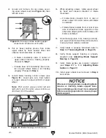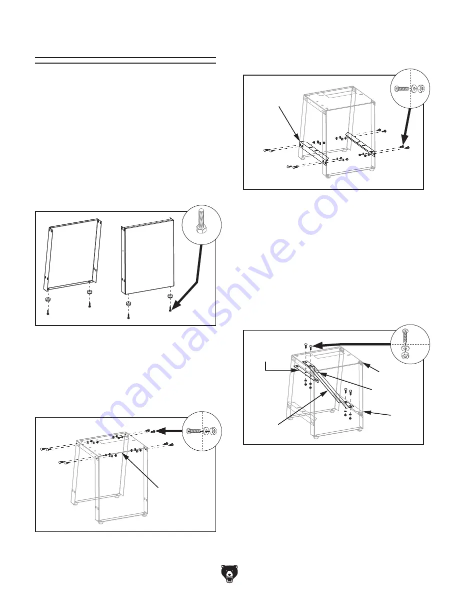
Figure 9. Attaching feet to stand legs.
Stand Top
Figure 10. Attaching stand legs to stand top.
Side Brace
(1 of 2)
Figure 11. Attaching side braces to stand legs.
Upper
Brace
Motor
Mount
Rear
Side
Brace
Clamp
Hole
Stand Top
Figure 12. Attaching motor mount to stand.
x 4
x 8
x 8
x 4
-16-
Model T32304 (Mfd. Since 02/21)
3. Attach side braces to stand legs with (8)
M8-1.25 x 16 carriage bolts, 8mm flat wash-
ers, and M8-1.25 hex nuts (see
Figure 11).
4. Attach motor mount to upper brace through
stand top with (2) M8-1.25 x 16 carriage
bolts, 8mm flat washers, and M8-1.25 hex
nuts (see
Figure 12), then attach motor
mount to rear side brace with (2) M8-1.25
x 16 carriage bolts, 8mm flat washers, and
M8-1.25 hex nuts.
IMPORTANT: Verify clamp hole on motor
mount is positioned on top (see
Figure 12)
before proceeding to the next step.
Assembly
To assemble machine:
1. Insert (4) M6-1 x 20 hex bolts into rubber feet,
and attach feet to each corner on stand legs
(see
Figure 9).
2. Attach stand legs to stand top with (8)
M8-1.25 x 16 carriage bolts, 8mm flat wash-
ers, and M8-1.25 hex nuts (see
Figure 10).
Note: DO NOT completely tighten fasteners
until instructed to in
Step 5.
The machine must be fully assembled before it
can be operated. Before beginning the assembly
process, refer to
Needed for Setup and gather
all listed items. To ensure the assembly process
goes smoothly, first clean any parts that are cov-
ered or coated in heavy-duty rust preventative (if
applicable).
5. Make sure stand top is centered over stand
sides and tighten all loose hex nuts.
Summary of Contents for T32304
Page 52: ......


