Straightedge
Belt Pulley
Motor
Touching Evenly
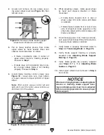
Figure 17. Checking pulley alignment with a
straightedge.
Clamp Hole
Figure 18. Motor mount clamp hole location
(components removed for clarity).
Table
Lock
Table Slot
Open End
Figure 19. Table lock located, and open table
slot aligned with blade.
-18-
Model T32304 (Mfd. Since 02/21)
10. Hold a straightedge close to the center of
both pulleys, and make sure straightedge
fully extends across rims of both pulleys, as
shown in
Figure 17.
— If pulleys are parallel and coplanar,
straightedge will touch the top and bottom
rims on both pulleys. No further adjust-
ment is required.
— If pulleys are parallel but not coplanar,
straightedge will touch the top and bot-
tom rims on one pulley, but will not touch
either rim on the other pulley. In this case,
loosen (4) carriage bolts securing motor
mount, then re-position motor so straight-
edge touches the top and bottom rims on
both pulleys. Repeat
Steps 9–10.
11. Connect motor power cord to power cord
receptacle on rear ON/OFF switch housing,
and secure to motor mount clamp hole (see
Figure 18) with cable holder.
12. Verify table lock location (see Figure 19), and
align open end of table slot with blade.
Summary of Contents for T32304
Page 52: ......


