-34-
Model T32338 (Mfd. Since 12/20)
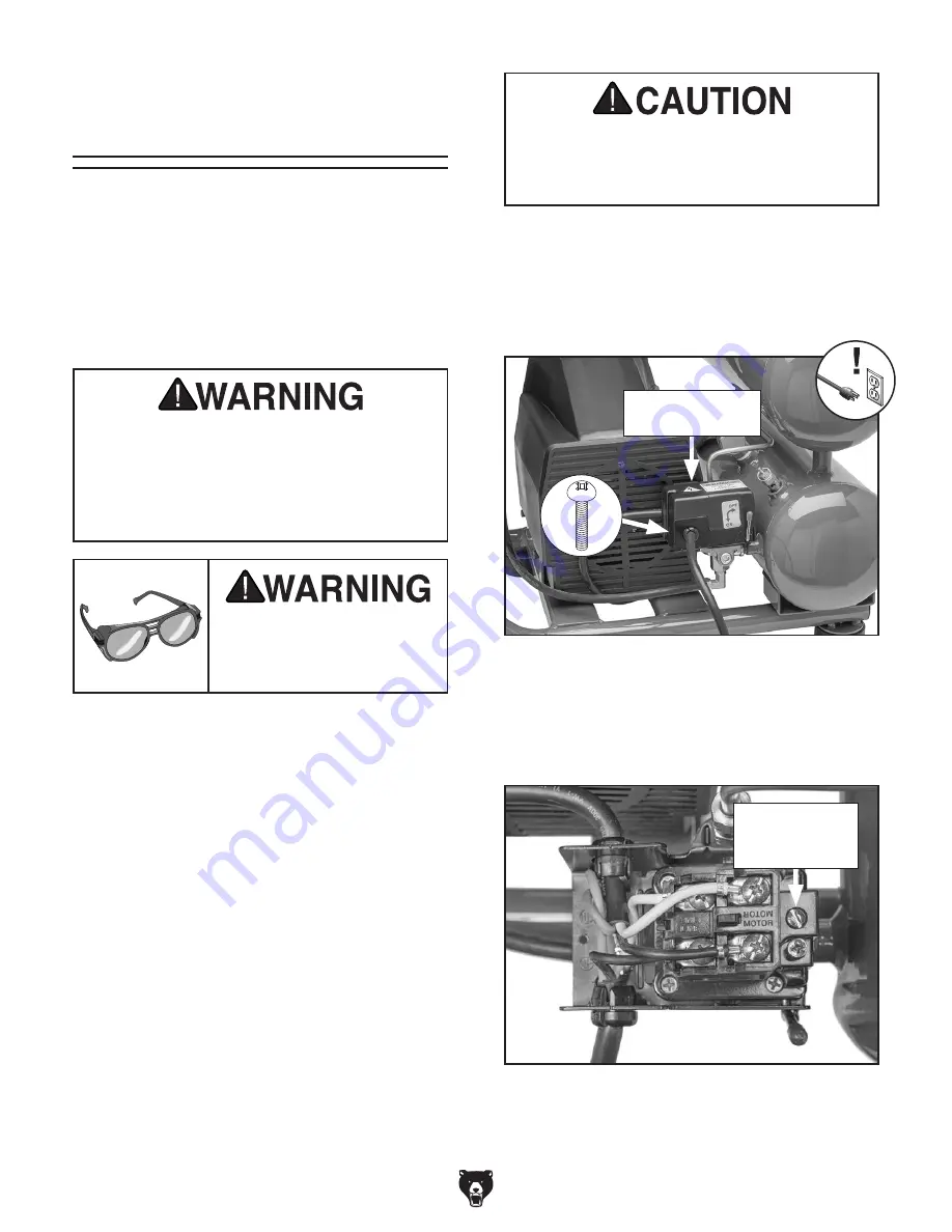
Figure 41. Location of pressure switch cover
Phillips head screw.
Pressure Switch
Cover
Releasing air through safety relief valve
can be extremely loud. Protect hearing with
ANSI-approved hearing protection while
performing following step.
3. Use safety relief valve to reduce tank pres-
sure to less than 10 PSI.
4. Remove Phillips head screw shown in
Figure 41 to remove pressure switch cover.
5. Adjust screw shown in Figure 42 to change
minimum and maximum tank pressure
settings.
Figure 42. Location of cut-in/cut-out adjustment
screw.
Cut-In/Cut-Out
Adjustment
Screw
To adjust cut-in/cut-out settings:
1. Operate compressor and record cut-in and
cut-out pressures.
2. DISCONNECT MACHINE FROM POWER!
Adjusting Cut-In/
Cut-Out Settings
The pressure switch ensures the compressor will
turn
ON when the tank pressure drops to approxi-
mately 95 PSI (cut-in pressure), and will turn
OFF
when the tank pressure reaches 125 PSI (cut-out
pressure). Should the pressure switch fail to turn
OFF the machine, the safety relief valve will open
shortly after the pressure exceeds 125 PSI and
prevent over-pressurization.
Cut-in and cut-out settings have been
factory set at proper PSI range. Only adjust
pressure switch settings if compressor
is cutting-in or cutting-out at incorrect
pressures. Tanks could burst if filled with
more pressure than it is designed for.
Eye injury hazard! Always
wear safety glasses when
handling pressurized air
system.
Tools Needed
Qty
Phillips Head Screwdriver #2 ............................ 1
Flat Head Screwdriver
1
⁄
4
" .................................. 1
Adjusting Cut-In/Cut-Out Settings
If the minimum and maximum tank pressure set-
tings both have to be raised or lowered at the
same time, then follow these steps.


