Model T32339 (Mfd. Since 03/21)
-37-
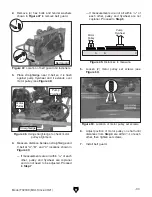
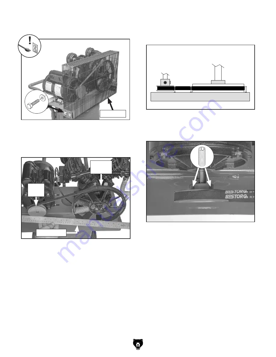
2. Remove (4) hex bolts and fender washers
shown in
Figure 47 to remove belt guard.
Figure 47. Location of belt guard and fasteners.
x 4
Belt Guard
3. Place straightedge near V-belt so it is flush
against pump flywheel and it extends over
motor pulley (see
Figure 48).
Figure 48. Using straightedge to check motor
pulley alignment.
A
B
C
Motor
Pulley
Pump
Flywheel
Figure 49. Distances to measure.
Straightedge
Motor
Pulley
Pump
Flywheel
4. Measure distance between straightedge and
V-belt at "A", "B", and "C" locations shown in
Figure 49.
— If measurements are all within
1
⁄
16
" of each
other, pulley and flywheel are coplanar
and do not need to be adjusted. Proceed
to
Step 7.
Figure 50. Location of motor pulley set screws.
6. Adjust position of motor pulley on shaft until
distances from
Step 4 are within
1
⁄
16
" of each
other, then tighten set screws.
7. Install belt guard.
5. Loosen (2) motor pulley set screws (see
Figure 50).
— If measurements are not all within
1
⁄
16
" of
each other, pulley and flywheel are not
coplanar. Proceed to
Step 5.
Summary of Contents for T32339
Page 48: ......


