background image

Model T32339 (Mfd. Since 03/21)

-39-

READ ELECTRICAL SAFETY 

ON PAGE 38!

Motor Rewired 
for 230V

1

4

2

6

6-15 Plug

Hot

Hot

Ground

230

VAC

G

LINE

MOTOR

LEFOO LF10-4H

PRESSURE

SWITCH

GND

Neutral

Hot

Ground

115 VAC

5-15 Plug

MOTOR 115V/230V

Run

Capacitor

30uF 370V

Start

Capacitor

189-227uF 165V

(Rewired for 230V)

(As Recommended)

1

4

2

6

(Rewired for 230V)

Motor Prewired 
for 115V

Wiring


Diagram

Summary of Contents for T32339

Page 1: ...F THIS MANUAL MAY BE REPRODUCED IN ANY SHAPE OR FORM WITHOUT THE WRITTEN APPROVAL OF GRIZZLY INDUSTRIAL INC CS22295 PRINTED IN USA V1 06 22 MODEL T32339 20 GALLON 2 HP PORTABLE AIR COMPRESSOR OWNER S MANUAL For models manufactured since 03 21 Keep for Future Reference ...

Page 2: ...ng grinding tool integrity and the usage of personal protective equipment The manufacturer will not be held liable for injury or property damage from negligence improper training machine modifications or misuse Some dust created by power sanding sawing grinding drilling and other construction activities contains chemicals known to the State of California to cause cancer birth defects or other repr...

Page 3: ...9 Operation Overview 19 Choosing Air Hose 20 Connecting Air Tool 21 SECTION 5 ACCESSORIES 23 SECTION 6 MAINTENANCE 24 Schedule 24 Draining Tank 25 Lubrication 25 Checking Air Filters 26 Checking Adjusting Belt Tension 27 Checking for Leaks 28 Machine Storage 29 SECTION 7 SERVICE 30 Troubleshooting 30 Inspecting Check Valve 33 Adjusting Cut In Cut Out Settings 35 Aligning Motor Pulley to Pump Flywh...

Page 4: ... Technical Support for help Before calling make sure you write down the manufacture date and serial number from the machine ID label see below This information is required for us to provide proper tech support and it helps us determine if updated documentation is available for your machine Manufacture Date Serial Number Manual Accuracy INTRODUCTION If you have questions need help need warranty inf...

Page 5: ...ns of the controls and features shown below to better understand the instructions in this manual Handle Machine Foot 1 of 2 Compressor Pump Tank Air Filter 1 of 2 Motor Motor Reset Button Wheel 1 of 2 Belt Guard Tank Pressure Gauge Exhaust Tube Safety Relief Valve Discharge Line Drain Valve Quick Connect Port Line Pressure Gauge Regulator Oil Sight Glass Pressure Switch ...

Page 6: ...e cautions are overlooked or ignored seri ous personal injury may occur No list of safety guidelines can be com plete Every shop environment is different Always consider safety first as it applies to your individual working conditions Use this and other machinery with caution and respect Failure to do so could result in serious personal injury damage to equip ment or poor work results Air Input Fi...

Page 7: ...25 PSI cut out pressure L Safety Relief Valve Pops open to release tank pressure in the event that pressure switch fails to stop motor at cut out pressure M Pressure Switch Turns motor ON when tank pressure drops below 95 PSI cut in pressure and switch is in AUTO position Switch contains pressure relief valve that will activate discharge line when tank pressure exceeds 125 PSI cut out pressure or ...

Page 8: ...ctrical Power Requirement 115V or 230V Single Phase 60 Hz Prewired Voltage 115V Full Load Current Rating 15A at 115V 7 5A at 230V Minimum Circuit Size 20A at 115V 15A at 230V Connection Type Cord Plug Power Cord Included Yes Power Cord Length 72 in Power Cord Gauge 12 AWG Plug Included Yes Included Plug Type 5 15 Recommended Plug Type 6 15 for 230V Switch Type Pressure Switch w Motor Reset Button ...

Page 9: ... Equivalent Air Compressor Oil Drain Valve Type Ball Valve Regulator Yes Output Port Information Connection Type Quick Coupler Connection Size 1 4 NPT Number of Connections 1 Hose Included No Construction Information Tank Steel Valves Brass Coated Paint Type Finish Enamel Other Specifications Country of Origin USA Warranty 1 Year Serial Number Location ID Label Features 20 Gallon Tank with Maximum...

Page 10: ...id proof DANGEROUS ENVIRONMENTS Do not use machinery in areas that are wet cluttered or have poor lighting Operating machinery in these areas greatly increases the risk of accidents and injury MENTAL ALERTNESS REQUIRED Full mental alertness is required for safe operation of machin ery Never operate under the influence of drugs or alcohol when tired or when distracted For Your Own Safety Read Instr...

Page 11: ... moving parts or flying debris Make sure they are properly installed undamaged and working correctly BEFORE operating machine FORCING MACHINERY Do not force machine It will do the job safer and better at the rate for which it was designed NEVER STAND ON MACHINE Serious injury may occur if machine is tipped or if the cutting tool is unintentionally contacted STABLE MACHINE Unexpected movement dur i...

Page 12: ...res sor pump parts heat up during operation Do not touch these parts during or immediately following operation to prevent burns MOVING AND SERVICING Disconnect power allow compressor to cool bleed air from system and disconnect attachment tools and hoses before moving or servicing to prevent impact injuries soft tissue injuries and burns TANK INTEGRITY Inspect tank attachment tools pump air lines ...

Page 13: ...n and make sure it is connected to a power supply circuit that meets the specified circuit requirements For your own safety and protection of property consult an electrician if you are unsure about wiring practices or electrical codes in your area Note Circuit requirements in this manual apply to a dedicated circuit where only one machine will be running on the circuit at a time If machine will be...

Page 14: ...uirements 115V Minimum Gauge Size 12 AWG 230V Minimum Gauge Size 18 AWG Maximum Length Shorter is Better 50 ft Grounding Requirements This machine MUST be grounded In the event of certain malfunctions or breakdowns grounding reduces the risk of electric shock by providing a path of least resistance for electric current Figure 6 Typical 5 15 plug and receptacle Grounding Pin Neutral Hot 5 15 PLUG G...

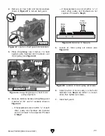
Page 15: ...ing cover Converting Voltage to 230V Items Needed Qty Flat Head Screwdriver 1 4 or Wrench 1 4 1 Phillips Head Screwdriver 2 1 NEMA 6 15 Plug 1 Figure 8 Location of motor wiring cover and bolts 3 Move white motor wire from terminal 4 to ter minal 2 see Figures 9 10 LINE MOTOR LEFOO LF10 4H PRESSURE SWITCH GND nd 1 4 2 6 Figure 9 Motor wired for 115V power supply 6 15 Plug Hot und G LINE MOTOR PRESS...

Page 16: ...hine can cause electrocution if live electrical wires make contact with frame or other parts touched by operator Figure 11 Location of pressure switch cover and screw 5 Remove screw shown in Figure 11 to remove pressure switch cover LINE MOTOR LEFOO LF10 4H PRESSURE SWITCH GND Neutral Hot Ground 115 VAC 5 15 Plug Run Capacitor 30uF 370V Start Capacitor 189 227uF 165V 1 4 2 6 Ground Wire Power Supp...

Page 17: ... shipping damage If items are damaged please call us immediately at 570 546 9663 IMPORTANT Save all packaging materials until you are completely satisfied with the machine and have resolved any issues between Grizzly or the shipping agent You MUST have the original pack aging to file a freight claim It is also extremely helpful if you need to return your machine later Unpacking NOTICE If you canno...

Page 18: ...ce allocation Physical Environment The physical environment where the machine is operated is important for safe operation and lon gevity of machine components For best results operate this machine in a dry environment that is free from excessive moisture hazardous chemi cals airborne abrasives or extreme conditions Extreme conditions for this type of machinery are generally those where the ambient...

Page 19: ...ormation is understood Eye injury hazard Always wear safety glasses when handling pressurized air system The Test Run consists of verifying the following 1 The compressor oil level is sufficient 2 the motor powers up and runs correctly 3 the motor and pump turn OFF when the cut out pressure is reached and 4 the safety relief valve works correctly Figure 16 Location of pressure switch lever 5 Turn ...

Page 20: ...afety feature of check valve is NOT working properly and must be replaced before further using machine 11 Turn machine OFF and slowly pull safety relief valve ring to bleed pressure from tank see Figure 19 If safety relief valve bleeds pressure from tank and air stops leaking when pressure is released then safety feature of safety relief valve is working correctly Proceed to Step 12 If safety reli...

Page 21: ... additional training outside of this manual Read books magazines or get formal training before beginning any proj ects Regardless of the content in this sec tion Grizzly Industrial will not be held liable for accidents caused by lack of training Do not touch compressor head or discharge line during use or immediately after compressor is active These hot parts may cause burns 3 Turns regulator knob...

Page 22: ...PT female quick coupler see Figure 22 so you will need a 1 4 NPT male plug attached to the hose Male Coupler Female Coupler Male Plug Female Plug Figure 22 Location of quick coupler outlet port Quick Coupler Length There are many options when it comes to hoses The most important aspects for an air compressor are going to be length diameter and fittings The material of the hose is also an important...

Page 23: ...sels grinders sanders tire inflators and paint sprayers Air hammers impact wrenches impact hammers and blow guns will probably require a larger compressor capable of 10 110 CFM Duty Cycle The duty cycle of your compressor will also have an effect on how efficient the airflow delivery is Refer to Figure 23 for some common duty cycles and what they mean Your second consideration should be the recom ...

Page 24: ...l the way counterclockwise Regulator Knob Figure 24 Location of regulator knob Disconnecting Air Tool To disconnect air tool 1 Turn regulator knob see Figure 24 all the way counterclockwise 2 Disconnect air tool from hose 3 Push coupler sleeve toward compressor to release hose plug see Figure 26 Note Air will escape when connection is bro ken if tank is still pressurized Figure 26 Pushing coupler ...

Page 25: ...artridge Filter Pair P100 Wood dust has been linked to nasal cancer and severe respiratory illnesses If you work around dust everyday a half mask respirator can be a lifesaver Also compatible with safety glasses Figure 28 Assortment of basic eye protection Basic Eye Protection T20501 Face Shield Crown Protector 4 T20502 Face Shield Crown Protector 7 T20503 Face Shield Window T20451 Kirova Clear Sa...

Page 26: ...to power and turned ON Do not touch compressor head or discharge line during use or immediately after compressor is active These hot parts may cause burns Allow compressor to cool before handling Eye injury hazard Always wear safety glasses when maintaining pressurized air system Compressor will turn ON automatically when pres sure switch is set to AUTO To reduce risk of shock accidental startup a...

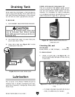
Page 27: ... valve to reduce tank pres sure to less than 10 PSI 3 Open drain valve see Figure 30 to drain condensation from tank Releasing air through safety relief valve can be extremely loud Protect hearing with ANSI approved hearing protection in following step Figure 32 Location of oil sight glass and oil fill plug Oil Sight Glass Oil Fill Plug Item Needed Qty Model T28041 or SAE 30 Equiv As Needed T28041...

Page 28: ...azard To check air filters 1 DISCONNECT MACHINE FROM POWER Checking Air Filters If filter is fairly clean and there has not been a drop in efficiency of compressor replace cap No replacement is required If filter is dirty or clogged or there has been a drop in efficiency of compressor replace cap Proceed to Step 4 4 Replace old filter with new filter element refer to Part 16 in Parts beginning on ...

Page 29: ... shown in Figure 35 to remove belt guard Figure 35 Location of belt guard and fasteners x 4 Belt Guard 3 Press belt in center to check belt tension Belt is correctly tensioned when there is approxi mately 1 4 deflection when it is pushed with moderate pressure as shown in Figure 36 Pulley Deflection Pulley 1 4 Figure 36 Checking V belt tension If V belt is in good condition and there is 1 4 of def...

Page 30: ...cation If bubbles do form proceed to Fixing Leaks Fixing Leaks 2 Use safety relief valve to reduce tank pres sure to less than 10 PSI 3 Open drain valve to relieve any remaining air 4 Remove fitting or valve that is leaking 5 Clean threads apply thread sealing tape or pipe dope to threads then re install part Note If a fitting or valve continues to leak after preceding steps replace part Item Need...

Page 31: ...wear safety glasses when handling pressurized air system Releasing air through safety relief valve can be extremely loud Protect hearing with ANSI approved hearing protection while performing following step 2 Use safety relief valve to reduce tank pres sure to less than 10 PSI 3 Open drain valve to drain any condensation from tank 4 Disconnect air tool and hose from machine 5 Clean machine T23951 ...

Page 32: ... replace fuse 6 Correct motor wiring connections Page 39 7 Test replace if at fault 8 Adjust centrifugal switch clean contact points Replace either if at fault 9 Fix broken wires or disconnected corroded connections Page 39 10 Reduce load on compressor and allow longer cool down periods 11 Clean replace check valve components Page 33 12 Turn compressor OFF disconnect from power and empty tank DO N...

Page 33: ...ged tank only replace 4 Turn compressor OFF disconnect from power and empty tank DO NOT USE until switch is replaced Pressure relief valve stays open and motor will not stop running 1 Pressure switch cut in cut out settings have been adjusted incorrectly 2 Pressure switch at fault unit is trying to overpressurize tank 3 Pressure relief valve at fault relieving pressure too early 1 Adjust settings ...

Page 34: ...ain oil to proper level Page 25 3 Adjust in line oiler drip ratio or use correct viscosity oil 4 Replace filter or in line filter assembly 5 Drain and replace with correct oil Page 25 6 Worn compressor piston rings or valves Rebuild or replace pump Air tools have watery discharge or get cold and freeze up with ice during use 1 Tank needs to be drained 2 In line water separator is full if used 3 Am...

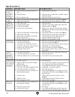
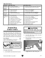
Page 35: ...th non flammable cleanser 2 Replace air filter s Page 26 3 Drain oil to proper level Page 25 4 Drain and replace with correct oil Page 25 5 Replace gasket or fill plug 6 Replace gasket s 7 Install cap screws with thread sealing tape 8 Tighten or replace valve plate ring 9 Replace crankcase or seal 10 Repair replace crankshaft Operation Cont Inspecting Check Valve The check valve allows the compres...

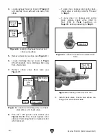
Page 36: ...t check valve elbow and check valve If valve does depress and spring back check valve is working correctly Proceed to Step 9 If valve does not depress and spring back replace check valve refer to Part 108 in Parts beginning on Page 41 before proceeding to Step 9 9 Install check valve check valve elbow dis charge line and exhaust tube Figure 43 Pressing valve disc with tool Valve Disc Depressed Elb...

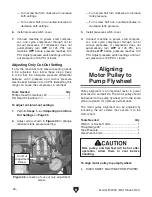
Page 37: ...uld burst if filled with more pressure than it is designed for Eye injury hazard Always wear safety glasses when handling pressurized air system Tools Needed Qty Phillips Head Screwdriver 2 1 Flat Head Screwdriver 1 4 1 Adjusting Cut In Cut Out Settings If the minimum and maximum tank pressure set tings both have to be raised or lowered at the same time then follow these steps Pressure Switch Cove...

Page 38: ...ew half turn clockwise to increase tank pressure Turn screw half turn counterclockwise to decrease tank pressure 3 Install pressure switch cover 4 Connect machine to power start compres sor and cycle compressor through cut in cut out pressures If compressor does not automatically turn OFF at 125 PSI turn machine OFF before pressure reaches 130 PSI Adjust pressure switch settings until cut out pres...

Page 39: ...e Straightedge Motor Pulley Pump Flywheel 4 Measure distance between straightedge and V belt at A B and C locations shown in Figure 49 If measurements are all within 1 16 of each other pulley and flywheel are coplanar and do not need to be adjusted Proceed to Step 7 Figure 50 Location of motor pulley set screws 6 Adjust position of motor pulley on shaft until distances from Step 4 are within 1 16 ...

Page 40: ...ent at the time of printing but may not match your machine If you find this to be the case use the wiring diagram inside the motor junction box CAPACITORS INVERTERS Some capacitors and power inverters store an electrical charge for up to 10 minutes after being disconnected from the power source To reduce the risk of being shocked wait at least this long before working on capacitors EXPERIENCING DI...

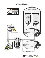
Page 41: ...1 4 2 6 6 15 Plug Hot Hot Ground 230 VAC G LINE MOTOR LEFOO LF10 4H PRESSURE SWITCH GND Neutral Hot Ground 115 VAC 5 15 Plug MOTOR 115V 230V Run Capacitor 30uF 370V Start Capacitor 189 227uF 165V Rewired for 230V As Recommended 1 4 2 6 Rewired for 230V Motor Prewired for 115V Wiring Diagram ...

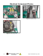
Page 42: ... 40 Model T32339 Mfd Since 03 21 READ ELECTRICAL SAFETY ON PAGE 38 Electrical Component Photos Figure 53 Capacitor wiring Figure 51 Pressure switch wiring Figure 52 Motor wiring 115V ...

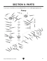
Page 43: ... 3 25 4 26 27 30 31 32 35 36 37 38 39 40 41 42 43 44 45 29 28 27 23 5 6 7 8 9 10 11 12 13 14 15 16 19 20 21 22 12 11 16 33 34 22 Pump SECTION 9 PARTS To order parts contact MEGA by phone at 832 415 6995 or email at CS megacompressor com ...

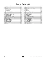
Page 44: ... HEX BOLT M8 1 25 X 20 8 33 HEX BOLT M8 1 25 X 35 4 10 CYLINDER GASKET UPPER 2 34 FLAT WASHER 8MM 4 11 VALVE DISC 51MM 2 35 CRANKSHAFT 1 12 REED VALVE 10 X 47 X 0 3MM 4 36 BALL BEARING 6205 OPEN 1 13 REED VALVE GASKET LOWER 2 37 OIL SEAL 1 14 REED VALVE GASKET UPPER 2 38 CRANKCASE COVER GASKET 1 15 HEAD GASKET 2 39 CRANKCASE COVER 1 16 AIR FILTER ASSEMBLY 2 40 LOCK WASHER 8MM 4 19 HEX BOLT M6 1 X ...

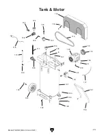
Page 45: ...Model T32339 Mfd Since 03 21 43 101 102 103 104 105 106 107 108 109 110 111 112 113 114 115 116 117 118 119 120 121 122 123 124 125 126 127 128 129 130 124 8 8 131 130 8 8 128 Tank Motor ...

Page 46: ...2 106 FLANGE BOLT M8 1 25 X 30 2 122 TEE FITTING 180 DEG 1 107 VIBRATION DAMPING RING 4 123 MOTOR 2HP 115V 230V 1 PH 1 108 CHECK VALVE 1 2 FLARE 1 124 PRESSURE GAUGE 2 109 ELBOW FITTING 90 DEG 1 125 PIPE NIPPLE 1 110 EXHAUST TUBE 1 126 REGULATOR 1 111 PUMP DISCHARGE LINE 1 127 QUICK COUPLER 1 4 NPT 1 112 MOTOR PULLEY 1 128 HEX BOLT M8 1 25 X 16 4 113 SET SCREW M4 7 X 10 1 129 HEX BOLT M8 1 25 X 30...

Page 47: ...with all guards covers and parts in place 10 Never leave machine running unattended 11 Avoid entanglement with moving parts tie back long hair roll up sleeves and do not wear loose clothing gloves or jewelry 12 DO NOT use if cord plug or any other electrical equipment becomes damaged promptly repair 13 DO NOT stand on compressor or obstruct airflow to ventilation 14 DO NOT exceed pressure rating o...

Page 48: ......

Reviews: