-4-
Model T32339 (Mfd. Since 03/21)
Controls &
Components
To reduce your risk of
serious injury, read this
entire manual BEFORE
using machine.
Refer to the following figures and descriptions to
become familiar with the basic controls and com-
ponents of this machine. Understanding these
items and how they work will help you understand
the rest of the manual and minimize your risk of
injury when operating this machine.
Like all machinery there is potential danger
when operating this machine. Accidents
are frequently caused by lack of familiarity
or failure to pay attention. Use this machine
with respect and caution to decrease the
risk of operator injury. If normal safety pre-
cautions are overlooked or ignored, seri-
ous personal injury may occur.
No list of safety guidelines can be com-
plete. Every shop environment is different.
Always consider safety first, as it applies
to your individual working conditions. Use
this and other machinery with caution and
respect. Failure to do so could result in
serious personal injury, damage to equip-
ment, or poor work results.
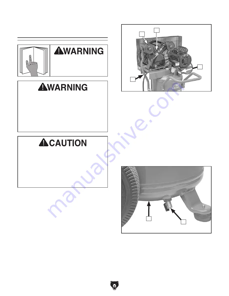
Air Input
Figure 1. Upper air input components.
A. Air Filter (1 of 2): Cleans air entering com-
pressor pump.
B. Compressor Pump: Uses pistons to draw in
and compress air before transferring air into
tank.
C. Tank Pressure Gauge: Indicates pressure
of air in tank.
D. Exhaust Tube: Transfers compressed air
from pump to tank.
Figure 2. Lower air input components.
E. Tank: Holds up to 20 gallons of pressurized
air.
F. Drain Valve: Drains built-up moisture from
tank when ball valve is opened.
F
E
D
A
B
C
Summary of Contents for T32339
Page 48: ......


