-4-
T32468 (Mfd. Since 02/21)
6. Measure machine base footprint size.
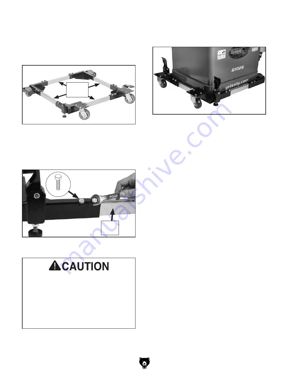
7. Slide corner brackets over ends of side rails
(see
Figure 9). Position corner brackets so
inside opening is
1
⁄
4
"–
1
⁄
2
" larger than both
width and length of machine base footprint.
Figure 9. Properly assembled mobile base with
inside opening slightly larger than machine base
to ensure easy fit.
Inside
Opening
9. With the help of an assistant or proper lifting
equipment, lift and position machine inside
mobile base (see
Figure 11).
Figure 11. Example of machine properly placed
inside mobile base.
10. Verify machine is properly seated on mobile-
base corner pads, it is free of wobbles, and
there is no deflection in mobile base.
—
Deflection: If any deflection exists, verify
all fasteners are securely tightened and
mobile base is properly assembled. If
this does not solve the problem, verify
machine does not exceed the rated weight
limit listed in
Specifications on Page 1.
—
Wobbles: Wobbles can easily be elimi-
nated by placing an appropriately sized
shim between machine and mobile base
where needed.
8. Secure each end of corner brackets with (2)
M8-1.25 x 16 hex bolts (see
Figure 10).
Figure 10. Securing corner bracket to rail with
BOTH hex bolts.
Side
Rail
BOTH hex bolts must be secured against
side rail in each end of corner brackets. DO
NOT load machine onto mobile base until all
bolts have been firmly tightened. Improper
tightening or using one bolt can result in
collapse or tipping when moving machine,
which could result in crushing injury or
property damage. DO NOT overtighten
bolts. Overtightening can strip threads.
x 2
Summary of Contents for T32468
Page 12: ......


