background image

-10-

Model T32719 (Mfd. Since 06/21)

NOTICE

If you cannot find an item on this list, care-

fully check around/inside the machine and 

packaging materials. Often, these items get 

lost in packaging materials while unpack-

ing or they are pre-installed at the factory.

Inventory

The following is a list of items shipped with your 
machine. Before beginning setup, lay these items 
out and inventory them.

If  any  non-proprietary  parts  are  missing  (e.g.  a 
nut or a washer), we will gladly replace them; or 
for the sake of expediency, replacements can be 
obtained at your local hardware store.

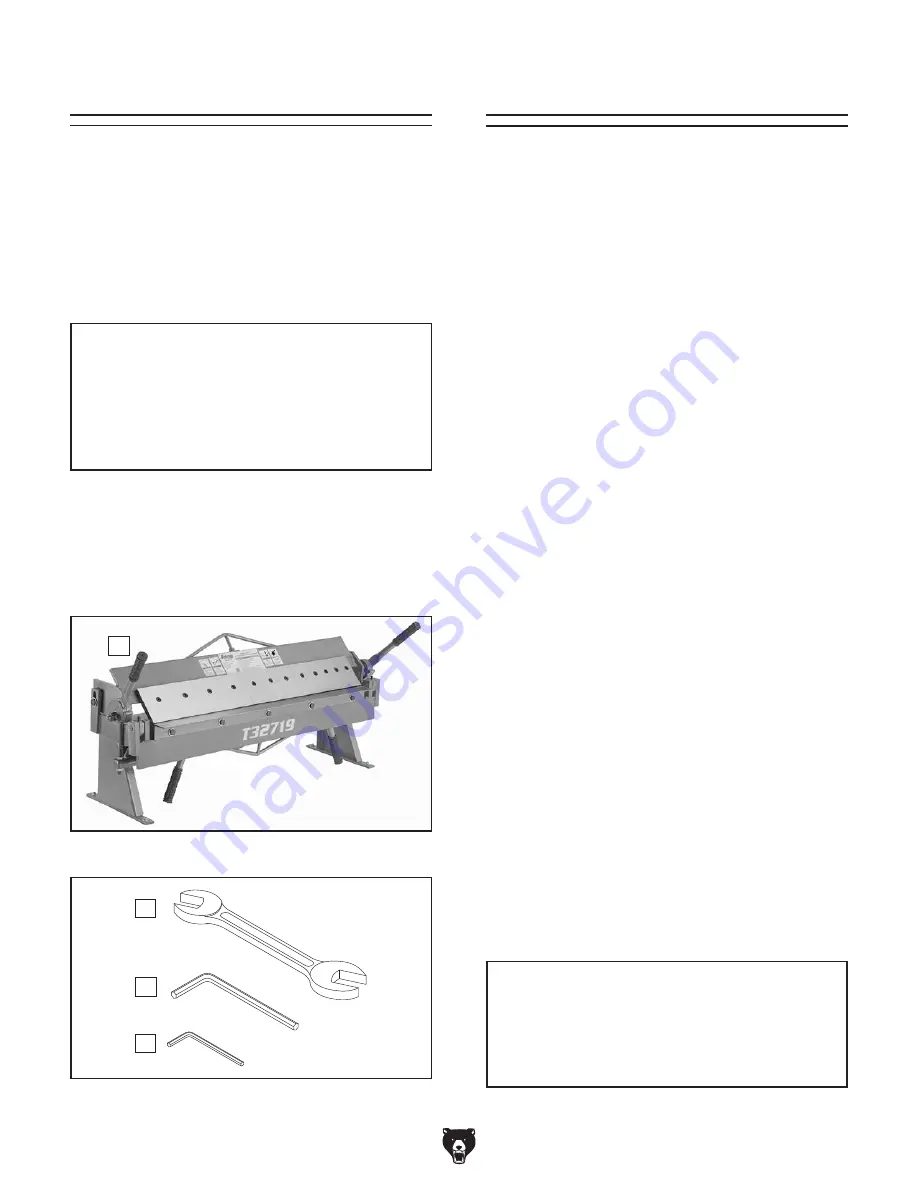
Inventory (Figures 3–4) Qty

A.  Pan & Box Brake ........................................ 1

B.  Open-End Wrench 17/19mm ...................... 1

C.  Hex Wrench 8mm ....................................... 1

D.  Hex Wrench 5mm ....................................... 1

Cleanup

The  unpainted  surfaces  of  your  machine  are 
coated  with  a  heavy-duty  rust  preventative  that 
prevents corrosion during shipment and storage. 
This rust preventative works extremely well, but it 
will take a little time to clean.

Be  patient  and  do  a  thorough  job  cleaning  your 
machine. The time you spend doing this now will 
give you a better appreciation for the proper care 
of your machine's unpainted surfaces.

There are many ways to remove this rust preven-
tative, but the following steps work well in a wide 
variety  of  situations.  Always  follow  the  manufac-
turer’s instructions with any cleaning product you 
use and make sure you work in a well-ventilated 
area to minimize exposure to toxic fumes.

Before cleaning, gather the following:
• 

Disposable rags

• 

Cleaner/degreaser (WD•40 works well)

• 

Safety glasses & disposable gloves

• 

Plastic paint scraper (optional)

Basic steps for removing rust preventative:

1.  Put on safety glasses.

2.  Coat  the  rust  preventative  with  a  liberal 

amount of cleaner/degreaser, then let it soak 
for 5–10 minutes.

3.  Wipe off the surfaces. If your cleaner/degreas-

er is effective, the rust preventative will wipe 
off easily. If you have a plastic paint scraper, 
scrape off as much as you can first, then wipe 
off the rest with the rag.

4.  Repeat Steps 2–3 as necessary until clean, 

then coat all unpainted surfaces with a quality 
metal protectant to prevent rust.

NOTICE

Avoid harsh solvents like acetone or brake 

parts cleaner that may damage painted sur-

faces. Always test on a small, inconspicu-

ous location first. 

B

C

D

Figure 4. Tools.

Cleanup

Figure 3. Pan and box brake.

A

Summary of Contents for T32719

Page 1: ...RNING NO PORTION OF THIS MANUAL MAY BE REPRODUCED IN ANY SHAPE OR FORM WITHOUT THE WRITTEN APPROVAL OF GRIZZLY INDUSTRIAL INC AI21939 PRINTED IN CHINA V1 07 21 MODEL T32719 36 BENCHTOP PAN BOX BRAKE OWNER S MANUAL For models manufactured since 06 21 ...

Page 2: ...ng grinding tool integrity and the usage of personal protective equipment The manufacturer will not be held liable for injury or property damage from negligence improper training machine modifications or misuse Some dust created by power sanding sawing grinding drilling and other construction activities contains chemicals known to the State of California to cause cancer birth defects or other repr...

Page 3: ...rs 11 Site Considerations 11 Lifting Placing 12 Bench Mounting 12 SECTION 3 OPERATIONS 13 Operation Overview 13 Spacing Fingers 14 Aligning Fingers 14 Adjusting Setback 15 Adjusting Clamping Pressure 16 Basic Bending 17 Bending Allowance 17 SECTION 4 ACCESSORIES 18 SECTION 5 MAINTENANCE 20 Schedule 20 Cleaning Protecting 20 Lubrication 20 SECTION 6 SERVICE 21 Troubleshooting 21 Aligning Bending Bl...

Page 4: ...made every effort to be exact with the instruc tions specifications drawings and photographs in this manual Sometimes we make mistakes but our policy of continuous improvement also means that sometimes the machine you receive is slightly different than shown in the manual If you find this to be the case and the difference between the manual and machine leaves you confused or unsure about something...

Page 5: ...this entire manual BEFORE using machine Become familiar with the names and locations of the controls and features shown below to better understand the instructions in this manual Bending Leaf Clamping Leaf Clamping Handles Bending Block Clamping Finger 1 of 12 Bending Handles Setback Wheels ...

Page 6: ...ned to allow clearance for workpiece D Bending Block Pivots with bending leaf to produce bend in workpiece E Clamping Pressure Adjustment Rod 1 of 2 Move up or down to set clamp ing pressure on workpiece according to workpiece gauge Lock rod in place with jam nuts F Bending Leaf Swivels up to bend workpiece G Bending Handle 1 of 2 Use to raise bend ing leaf and form bend in workpiece Figure 1 Cont...

Page 7: ...h x Height 50 x 17 x 22 in Must Ship Upright Yes Main Specifications Capacities Maximum Width 36 in Maximum Thickness at Half Width Mild Steel 16 Gauge Maximum Thickness at Full Width Mild Steel 18 Gauge Aluminum 16 Gauge Stainless Steel 20 Gauge Brake Range 0 135 deg Minimum Reverse Bend 5 16 in Maximum Height of Pan Box Brake Sides 2 in Number of Fingers 12 Width of Fingers 2 3 4 in Construction...

Page 8: ...id proof DANGEROUS ENVIRONMENTS Do not use machinery in areas that are wet cluttered or have poor lighting Operating machinery in these areas greatly increases the risk of accidents and injury MENTAL ALERTNESS REQUIRED Full mental alertness is required for safe operation of machin ery Never operate under the influence of drugs or alcohol when tired or when distracted For Your Own Safety Read Instr...

Page 9: ... moving parts or flying debris Make sure they are properly installed undamaged and working correctly BEFORE operating machine FORCING MACHINERY Do not force machine It will do the job safer and better at the rate for which it was designed NEVER STAND ON MACHINE Serious injury may occur if machine is tipped or if the cutting tool is unintentionally contacted STABLE MACHINE Unexpected movement dur i...

Page 10: ...ged components could result in sudden unexpected movements during use Inspect the brake for cracked compo nents damaged linkage levers or loose fasten ers Correct any problems before use LEAVING UNATTENDED To reduce the risk of crushing or amputation injuries with children or visi tors lower the clamping leaf when not in use Hands fingers can be crushed or severely pinched if caught between clampi...

Page 11: ... completely satisfied with the machine and have resolved any issues between Grizzly or the shipping agent You MUST have the original pack aging to file a freight claim It is also extremely helpful if you need to return your machine later Unpacking This machine presents serious injury hazards to untrained users Read through this entire manu al to become familiar with the controls and opera tions be...

Page 12: ...ciation for the proper care of your machine s unpainted surfaces There are many ways to remove this rust preven tative but the following steps work well in a wide variety of situations Always follow the manufac turer s instructions with any cleaning product you use and make sure you work in a well ventilated area to minimize exposure to toxic fumes Before cleaning gather the following Disposable r...

Page 13: ...e all clamping fingers and thoroughly clean them To remove the clamping fingers move clamping handles see Figure 5 toward back of machine to raise the clamping leaf then loosen the cap screws and remove the clamping fingers and toe clamps see Figure 6 Figure 5 Location of clamping handle and fingers Clamping Handle 1 of 2 Clamping Finger 1 of 12 After all fingers have been cleaned coat them libera...

Page 14: ...g holes that allow it to be fastened to a workbench or other mounting surface to prevent it from moving during operation and causing accidental injury or damage The strongest mounting option is a Through Mount see example below where holes are drilled all the way through the workbench and hex bolts washers and hex nuts are used to secure the machine in place Machine Base Workbench Hex Bolt Flat Wa...

Page 15: ...ger spacing 3 Adjusts clamping pressure for workpiece thickness 4 Correctly adjusts setback 5 Puts on safety glasses leather boots and leather gloves 6 Properly positions workpiece underneath clamping fingers and lowers clamping leaf to secure workpiece 7 With body square to brake and using both hands raises bending leaf to form correct bend angle 8 Lowers bending leaf and removes workpiece If you...

Page 16: ...f the fingers so that you can space the others to match the inside width of your pan or box Spacing Fingers Figure 10 Example of finger spacing Item s Needed Qty Hex Wrench 8mm 1 To space clamping fingers 1 Loosen cap screw on each finger you need to remove 2 Remove fingers and toe clamps from clamp ing leaf as shown in Figure 10 and set them aside Note You may need to mix and match finger widths ...

Page 17: ...ng Surface Edge View A 11 2 x A Bending Leaf Setback Distance Finger 4 Rotate both setback wheels until desired set back distance is achieved Note Setback wheels are eccentric Turning them one full turn will bring clamping leaf back to its original position Tip If you find it hard to turn setback wheels with your fingers insert a hex wrench into the holes on edges of wheels to gain leverage 5 Lowe...

Page 18: ...d of brake and 2 o clock viewed from left end of brake position then clamping pressure is suit able for workpiece Proceed to Step 4 If clamping handles are not at 10 o clock viewed from right end of brake and 2 o clock viewed from left end of brake position then clamping pressure is not suitable for workpiece Proceed to Step 2 2 Loosen adjustment nuts see Figure 14 and turn both sets up or down un...

Page 19: ...of each bend especially when more than one bend is required This is called bend allowance As a rule of thumb subtract the bend allowance from the sum of the workpiece outside dimen sions to obtain the overall length and width of the blank needed to make a particular part Exact allowances can only be obtained by trial and error due to differences in sheet metal hard ness whether the bend is with or...

Page 20: ...ng unpainted cast iron steel parts on machinery Recommended Metal Protectants G5562 SLIPIT 1 Qt Gel G5563 SLIPIT 12 Oz Spray G2870 Boeshield T 9 4 Oz Spray G2871 Boeshield T 9 12 Oz Spray H3788 G96 Gun Treatment 12 Oz Spray H3789 G96 Gun Treatment 4 5 Oz Spray Figure Recommended products for protecting unpainted cast iron steel parts on machinery recommended metal protectants T23692 Orange Power D...

Page 21: ...o it s perfect for wet or oily conditions Measures 3 wide x 5 long x 3 8 thick Figure Model T10456 Anti Fatigue Mat Figure 19 T10456 Anti Fatigue Mat H5503 Electric Sheet Metal Shear Motor 1 2 HP 110V 2500 RPM 3 8 Amp Swivel head adjust 360 Variable speed 0 2500 RPM Cuts up to 14 gauge in mild steel and 18 gauge in stainless at up to 150 in min Weighs 5 lbs Figure 21 H5503 Electric Sheet Metal She...

Page 22: ...injury and maintain proper machine operation stop operations immediately if you ever observe any of the items below and fix the problem before continuing Loose mounting bolts Worn or damaged clamping fingers Any other unsafe condition Daily Maintenance Lubricate clamping leaf pivots Lubricate bending leaf pivots Weekly Maintenance Lubricate clamping leaf guide pin slots Figure 23 Lubrication point...

Page 23: ...d 2 Not enough setback 1 Use sheet metal gauge thickness size within machine capacities Page 5 2 Properly calculate and adjust setback Page 15 Bend radius not consistent along workpiece 1 Clamping fingers not aligned 2 Bending block not flush with bending leaf 3 Too much setback 1 Properly align clamping fingers Page 14 2 Properly align bending block Page 22 3 Properly calculate and adjust setback...

Page 24: ...ed use Item s Needed Qty Open End Wrench 17mm 1 To align bending block 1 Look closely along tops of bending block and bending leaf see Figure 24 to determine if they are out of alignment Figure 24 Location of hex bolts for aligning bending block 3 Align bending block flush with bending leaf and then tighten hex bolts Top of Bending Leaf Top of Bending Block Hex Bolt 1 of 5 2 Loosen 5 hex bolts see...

Page 25: ...G 4 PT32719004 SWIVEL ROD RIGHT 18 PT32719018 BENDING LEAF PIVOT SHAFT 5 PT32719005 FLAT WASHER 16MM 19 PT32719019 BENDING LEAF 6 PT32719006 CAP SCREW M6 1 X 16 20 PT32719020 BENDING BLOCK 7 PT32719007 CLAMPING LEAF 21 PT32719021 HEX BOLT M12 1 75 X 20 8 PT32719008 SWIVEL ROD LEFT 22 PT32719022 WRENCH 17 X 19MM OPEN ENDS 9 PT32719009 HANDLE LEFT 23 PT32719023 HEX WRENCH 5MM 10 PT32719010 TOE CLAMP...

Page 26: ...n and leather gloves 3 Secure brake to floor before using 4 Chamfer and deburr sharp metal edges before bending 5 Do not exceed rated capacity 6 Do not use breaker bar to gain leverage 7 Do not bend wire or nails 8 Always keep hands and fingers away from clamping block and bending fingers when raising lowering bending leaf 9 Do not operate under influence of drugs or alcohol or when tired 10 Preve...

Page 27: ...erty or for incidental contingent special or consequential damages arising from the use of our products The manufacturers reserve the right to change specifications at any time because they constantly strive to achieve better quality equipment We make every effort to ensure that our products meet high quality and durability standards and we hope you never need to use this warranty In the event you...

Page 28: ......

Reviews: