background image

6

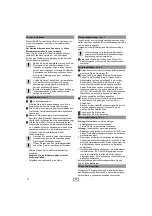
This GROHE fitting can be used in conjunction with 
a pressurised storage heater or an instantaneous heater.

Operation with unpressurised storage heaters 
( = open water heaters) is not possible.

To ensure correct operation of the fitting, the flow 
pressure should be between 1 and 5 bar.
It is recommendable to install a pressure-reducing valve 
in the case of higher flow pressures.

In the case of new installations, flush the cold 
and hot water lines thoroughly until the water is 
completely free of contamination before and 
after installation. Otherwise any residues 
remaining in the lines may block the fitting and 
contaminate the drinking water.
Make sure that you do not damage the fitting 
surfaces with the tool during installation. For this 
reason, never use toothed pliers.
Never install shut-off valves in the outlet pipe 
(mixed water) downstream of any concealed 
mixer.

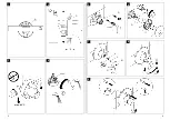
1

= Figure number

Drill the hole for the fitting and cut the slots for the 
pipes in the installation wall.

1

Align the fitting using a spirit level. The arrows on the 
fitting template 

A

 must point upwards.

2

Install the fitting using the fitting template 

B

. Ensure 

that the finished surface of the wall 

C

 lies within the 

area 

X

 of the fitting template.

3

Apply sealing compound at the cold, hot and mixed 
water connection pipes in accordance with their 
overall installation. Screw the connection pipes into 
the fitting body before installing the fitting.

- Attach the connecting pipes to the overall installation.

Note that soldered connections are not 
permitted as otherwise built-in seals may be 
damaged.
Open the cold and hot water supply and check 
the connections for watertightness.

- Shut off the hot and cold water supply again.

- Only remove the fitting template for final 

installation.

- Plaster and tile the wall.

This fitting is equipped with a flow rate limiter, permitting 
an infinitely variable individual reduction in flow rate.
The highest possible flow rate is set at the factory before 
despatch.

The use of flow rate limiters in combination with 
hydraulic instantaneous heaters is not 
recommended.

4

Change the flow rate by turning the adjusting screw 
using a 2.5mm allen key.

5

Remove screw plug 

D

 and install diverter 

E

.

6

Screw on the cap 

G

 with the seal. Grease the seal 

H

Push on the wall plate 

I

 and secure it with screws

I1

Push on the escutcheon 

J

.

If you cannot push the escutcheon far enough onto 
the cap 

G

, you must install an extension, see 

Replacement Parts, Page 1 (46 191 = 25mm 
or 46 343 = 50mm). If the wall surface is uneven, the 
top edge of the escutcheon must additionally be 
sealed with silicone.

7

Fit the insulator 

K

 onto the cartridge switch lever and 

secure it using the screw 

L

.

Fit the lever 

M

 and fasten it with the loosely fitted set 

screw 

N

 and insert the plug 

O

.

8

Operate the fitting as shown.

9

Operate the diverter as shown.

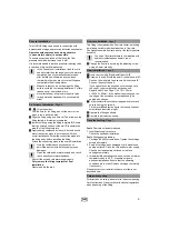
Fault: 

Flow rate noticeably reduced

1. Insufficient supply pressure:

Check the upstream installation.

Fault:

 Fitting housing leaking

1. Cartridge (46 048) screws loose: Tighten the cartridge 

screws alternately.

2. Seals at cartridge base damaged or dirt particles on 

sealing surfaces: Close the cold and hot water supply. 
Check and clean sealing surfaces, or replace 
cartridge completely.

3. Impermissible operating conditions, such as hot water 

temperature above 80 °C, pressure surges in 
upstream installation: Ensure that the operating 
conditions are in order. Replace cartridge completely 
if necessary.

Please contact your installer in the event of faults not 
described here.

For directions on care, please refer to the accompanying 
Care Instructions. Observe the valid national regulations 
when disposing of the fitting.

Prior to installation

Preliminary installation

, Page 3

Flow rate limitation

, Page 3

Final installation

, Page 4

Troubleshooting

, Page 1

Care and recycling

GB

Summary of Contents for 29 082

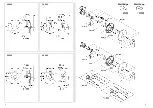
Page 1: ... 23 RUS 27 E 4 DK 8 UAE 12 P 16 HR 20 LT 24 Design Engineering GROHE Germany 99 0066 031 ÄM 226476 01 13 StartE dge StratLoop D 5 I 9 CZ 13 HR 17 DK 21 LV 25 GB 6 NL 10 H 14 RO 18 N 22 LT 26 F 7 PL 11 P 15 TR 19 FIN 23 UA 27 E 8 GR 12 SLO 16 S 20 EST 24 RUS 28 StartEdge StartLoop 29 082 29 083 29 084 29 085 ...

Page 2: ...2 1 StartEdge StartLoop 29 082 29 082 29 083 29 085 ...

Page 3: ...4 3 2 B X C 3 max 80 C 1 A 5 D E 17mm 6 G H I J I1 7 M N O K L 3mm 8 4 2 5mm 9 ...

Page 4: ...en Werkseitig ist der größtmögliche Durchfluss voreinge stellt In Verbindung mit hydraulischen Durchlaufer hitzern ist der Einsatz der Durchflussmengen begrenzung nicht zu empfehlen 4 Verändern Sie den Durchfluss durch Drehen der Einstellschraube mit einem 2 5mm Innensechskant schlüssel 5 Schrauben Sie die Verschlussschraube D heraus und montieren Sie die Umstellung E 6 Schrauben Sie die Kappe G m...

Page 5: ...ting is equipped with a flow rate limiter permitting an infinitely variable individual reduction in flow rate The highest possible flow rate is set at the factory before despatch The use of flow rate limiters in combination with hydraulic instantaneous heaters is not recommended 4 Change the flow rate by turning the adjusting screw using a 2 5mm allen key 5 Remove screw plug D and install diverter...

Page 6: ... une limitation individualisée et en continu du débit Le débit maximal est préréglé en usine L utilisation du limiteur de débit est déconseillée avec des chauffe eau instantanés à commande hydraulique 4 Modifier le débit en tournant la vis de réglage avec une clé Allen de 2 5mm 5 Dévisser la vis de fermeture D et monter l inverseur E 6 Dévisser le cache G avec le joint Lubrifier le joint H Insérer...

Page 7: ...uede limitar el caudal de forma progresiva e individual El ajuste de fábrica corresponde al máximo caudal posible Se recomienda no utilizar el limitador de caudal en combinación con calentadores instantáneos con control hidráulico 4 Modificar el caudal girando el tornillo de ajuste con una llave de macho hexagonal de 2 5mm 5 Desenroscar el tapón roscado D y montar la inversión E 6 Desenroscar la t...

Page 8: ... individuale Il rubinetto viene regolato di fabbrica sulla portata massima L uso del limitatore di portata non è raccomandabile negli scaldabagni istantanei idraulici 4 Modificare la portata ruotando la vite di regolazione con una chiave a brugola da 2 5mm 5 Svitare il tappo a vite D e montare il deviatore E 6 Avvitare il cappuccio G con la guarnizione Ingrassare la guarnizione H Inserire la piast...

Page 9: ...briek wordt de maximale capaciteit afgesteld In combinatie met c v ketels met warmwatervoorziening en geisers is het gebruik van de doorstroombeperking aan de warmwaterkant niet aan te raden i v m de tapdrempel van de geiser combiketel 4 Verander de capaciteit door de inbusbout met een inbussleutel van 2 5mm te draaien 5 Schroef afsluitbout D los en monteer omstelling E 6 Schroef de kap G met de p...

Page 10: ...Przepływ nastawiono fabrycznie na wartość maksymalną Wykorzystanie funkcji ogranicznika przepływu wody w połączeniu z włączanymi ciśnieniowo przepływowymi podgrzewaczami wody nie jest zalecane 4 Obracając śrubą z gniazdem sześciokątnym przy pomocy klucza imbusowego 2 5mm można teraz zmienić natężenie przepływu 5 Wykręcić śrubę zaślepiającą D i zamontować przełącznik E 6 Wkręcić kołpak G z uszczelk...

Page 11: ...λακάκια Αυτά τα εξαρτήµατα διαθέτουν έναν αναστολέα ροής Έτσι έχετε τη δυνατότητα να µειώσετε αδιαβάθµητα τη ροή του νερού Η εργοστασιακή ρύθµιση ισοδυναµεί µε τη µέγιστη δυνατή παροχή εν συνιστάται η σύνδεση του αναστολέα ροής µε υδραυλικούς ταχυθερµοσίφωνες 4 Μεταβάλλετε τη ροή µε περιστροφή της βίδας ρύθµισης µε εξάγωνο κλειδί 2 5mm 5 Ξεβιδώστε τη σύζευξη µε βίδες D και τοποθετήστε το διανοµέα ...

Page 12: ...podle potřeby individuálně omezit průtokové množství vody Z výroby je přednastaveno maximální průtokové množství vody Omezovače průtokového množství se nedoporučuje použít ve spojení s hydraulickými průtokovými ohřívači 4 Průtok nastavte otáčením seřizovacího šroubu pomocí klíče na vnitřní šestihrany 2 5mm 5 Vyšroubujte uzavírací šroub D a namontujte přepínání E 6 Našroubujte krytku G s těsněním T...

Page 13: ...gyedileg tudja az átfolyó mennyiséget korlátozni Gyárilag a lehető legnagyobb átfolyás van beállítva Hidraulikusan vezérelt átfolyó rendszerű vízmelegítőkkel nem javasoljuk a mennyiségkorlátozó használatát 4 Változtassa meg az átfolyó mennyiséget a beállítócsavarnak egy 2 5mm es imbuszkulccsal történő elfordításával 5 Tekerje ki az D zárócsavart majd szerelje fel az E átalakítót 6 Csavarozza fel a...

Page 14: ...o pode limitar o caudal de passagem de forma contínua e individual A regulação de origem foi feita para o caudal máximo Não é aconselhável a utilização de limitadores de caudal juntamente com esquentadores hidráulicos 4 A alteração do caudal é feita rodando o parafuso de ajuste com uma chave sextavada interior de 2 5mm 5 Remova o tampão roscado D e monte o inversor E 6 Enrosque a calota G com a ju...

Page 15: ...njska individualno nastavljiva omejitev količine pretoka Tovarniška nastavitev zagotavlja največji pretok V povezavi s hidravličnimi pretočnimi grelniki se ne priporoča omejevanje količine pretoka 4 Pretok spreminjate z vrtenjem nastavitvenega vijaka uporabite imbus ključ 2 5mm 5 Odvijte zaklopni vijak D in namestite preklopni del E 6 Privijte kapico G s tesnilom Namastite tesnilo H Namestite krov...

Page 16: ...ljena graničnikom količine Time je omogućeno kontinuirano individualno ograničavanje protoka Tvornički je namješten maksimalan protok Ograničavanje protoka ne preporučuje se ako se radi o hidrauličkim protočnim grijačima vode 4 Protok možete mijenjati okretanjem vijka za podešavanje imbus ključem od 2 5mm 5 Odvrnite zaporni vijak D i montirajte podešavanje E 6 Uvijte kapu G s brtvilom Podmažite br...

Page 17: ...e posibilă o limitare continuă individuală a debitului Din fabrică limitatorul este prereglat pentru debitul maxim posibil Nu se recomandă utilizarea limitatorului de debit la încălzitoarele hidraulice instantanee 4 Modificaţi debitul prin rotirea şurubului de reglaj folosind o cheie imbus de 2 5mm 5 Deşurubaţi şurubul de închidere D şi montaţi schimbătorul E 6 Deşurubaţi capacul G cu garnitura Un...

Page 18: ...rafından mümkün olan en fazla akışa ayarlanmıştır Hidrolik kumandalı ısıtıcıların kullanılması durumunda akış miktar sınırlayıcının montajı tavsiye edilmez 4 Akış miktarının değiştirilmesi bir ayar vidasının 2 5mm lik bir alyen anahtarı ile ayarlanması sayesinde olur 5 Kapak civatasını D sökün ve divertörü E monte edin 6 Kapağı G conta ile birlikte takın Contayı H yağlayın Kapak I ittirin ve vidal...

Page 19: ...smängden steglöst och individuellt Från fabrik är det största möjliga genomflödet förinställt Flödesbegränsningen bör inte användas i kombination med hydrauliska vattenvärmare 4 Ändra genomflödet genom att vrida inställningss kruven med en 2 5mm insexnyckel 5 Skruva loss skruvpluggen D och montera omkastaren E 6 Skruva på hylsan G med tätningen Fetta in tätningen H Skjut på täckplatta I och sätt f...

Page 20: ...kan begrænses trinløst og individuelt Fra fabrikken er den størst mulige gennemstrømning forindstillet I forbindelse med hydrauliske gennemstrømningsvandvarmere anbefales brug af gennemstrømningsbegrænsning ikke 4 Gennemstrømningen kan ændres ved at dreje indstillingsskruen med en unbrakonøgle 2 5mm 5 Skru låseskruen D ud og monter omstillingen E 6 Skru kappen på G med pakningen Fedt pakningen H i...

Page 21: ...iduell begrensning av strømningsmengden Den største mulige gjennomstrømningen er forhåndsinnstilt fra fabrikken Bruk av strømningsbegrenser anbefales ikke i forbindelse med hydrauliske varmtvannsberedere 4 Endre gjennomstrømningen ved å dreiejusteringss kruen med en 2 5mm unbrakonøkkel 5 Skru ut skrupluggen D og monter omkobleren E 6 Skru på kappen G med tetningen Smør tetningen H med fett Skyv på...

Page 22: ...irtausmäärää Tehtaalla läpivirtaus on esisäädetty suurimmalle mahdolliselle määrälle Läpivirtauksen rajoitinta ei suositella käytettäväksi yhdessä hydraulisten läpivirtauskuumentimien kanssa 4 Muuta läpivirtausta kiertämällä säätöruuvia 2 5mm n kuusiokoloavaimella 5 Ruuvaa sulkuruuvi D irti ja asenna vaihdin E 6 Ruuvaa suojus G tiivisteen kanssa paikalleen Rasvaa tiiviste H Työnnä peitelevy I paik...

Page 23: ...avalt vajadusele piirata Tehases on eelseadistatud suurim võimalik läbivool Voolumäära piirajat ei ole soovitatav kasutada ühendatuna hüdrauliliste läbivooluboileritega 4 Muutke läbivoolu keerates seadekruvi 2 5mm se sisekuuskantkruvikeeraja abil 5 Keerake keermega torukork D välja ja monteerige ümberlülitus E 6 Keerake keraamilise sisu kate G koos tihendiga peale Määrige tihendit H määrdega Lükak...

Page 24: ...ēc izvēles Sākotnēji rūpnīcā uzstādīts maksimāli iespējamais caurteces apjoms Neiesakām lietot apjoma ierobežotāju ja izmantojat caurteces ūdens sildītāju 4 Caurteces plūsmu var mainīt pagriežot iekšējā sešstūra skrūvi izmantojot 2 5mm iekšējā sešstūra atslēgu 5 Izskrūvējiet nosedzošo skrūvi D un uzstādiet regulatoru E 6 Uzskrūvējiet nosegu G kopā ar blīvējumu Ieziediet blīvējumu H Uzbīdiet pārsed...

Page 25: ...opų ir individualiai apriboti vandens pratakos kiekį Gamykloje nustatoma didžiausia galima vandens prataka Nerekomenduojame naudoti vandens pratakos kiekio ribotuvo kartu su hidrauliniais tekančio vandens šildytuvais 4 Nekeiskite vandens pratakos kiekio sukdami reguliavimo sraigtą 2 5mm šešiabriauniu varžtu 5 Išsukite srieginį kamštį D ir sumontuokite perjungiklį E 6 Užsukite gaubtelį G su tarpine...

Page 26: ...нього можна плавно відрегулювати силу потоку до необхідної величини Виробник встановлює регулятор сили потоку на максимум Не рекомендується використовувати регулятор сили потоку в системі з проточними водонагрівачами 4 Змініть пропускну здатність повертаючи регулювальний гвинт за допомогою шестигранного гайкового ключа діаметром 2 5 мм 5 Вигвинтіть різьбову пробку D та встановіть перемикач E 6 Виг...

Page 27: ...регулятором расхода Тем самым возможно индивидуальное бесступенчатое ограничение расхода На заводе изготовителе установлен максимальный уровень расхода Регулятор расхода не рекомендуется использовать в системе с гидравлическими проточными водонагревателями 4 Изменить расход воды поворачивая регулировоч ный винт шестигранным ключом на 2 5мм 5 Вывинтить резьбовую пробку D и установить переключатель ...

Page 28: ...у Изделие сертифицировано Grohe AG Германия Однорычажный смеситель Комплект поставки 29 082 29 083 29 084 29 085 скрытый смеситель X X X X надфундаментная часть X X надфундаментная часть переключатель X X Техническое руководство X X X X Инструкция по уходу X X X X Вес нетто кг 2 4 2 0 2 4 2 0 ...

Page 29: ......

Page 30: ......

Reviews: