background image

4

Electrical test data

• Software class:

A

• Contamination class:

1

• Rated surge voltage:

2500 V

• Temperature for ball impact test:

100 °C

The test for electromagnetic compatibility (interference 
emission test) was performed at the rated voltage and rated current.

Approval and conformity

The conformity declarations can be obtained from the following address:

GROHE Deutschland Vertriebs GmbH

Zur Porta 9
D-32457 Porta Westfalica

IMPORTANT NOTE! Note the following prior to installation:

• Avoid sharp bends or right angles in the steam pipe.
• Do not direct the steam jet against walls, seats or other objects. 

Keep a minimum of 700mm away from the steam nozzle.

• "Pockets of water" must not develop in steam and/or ventilation pipes. 

IMPORTANT NOTE! 

The flow rate inside the steam pipe must not be 

restricted (by a tap or valve). The inner diameter of the steam pipe must 
not be reduced in size in any way.

• In steambath rooms that operate continuously for more than two hours, 

the air must be changed at a rate of 10-20m³ per person per hour.

• The power supply cable to the steam generator must always be live. 

Do not connect any switches or similar devices to this cable.

• Outlet pipes between the steam generator and the waste water outlet 

must always be sloping downwards.

• The ambient temperature outside the vapour chamber and around the 

steam generator must not exceed 35 °C.

• Mount the feeler gauge diagonally as far away as possible from the 

steam outlet (at a height of 1500-1700mm).

• Descale the steam generator regularly according to the "Descaling" 

section of the instructions.

• Clean the steambath cubicle regularly. See section "Cleaning the 

steambath cubicle".

CAUTION!

 The waste water from the steam generator must always 

be routed into a waste water outlet outside the steambath cubicle. 
The waste water outlet must be designed to withstand 100° C hot water. 
The escaping water is hot. If the water hardness exceeds 5° dH, a water 
softener must be used.

• Vacant tubes EN21 must be used for the cables from the control unit to 

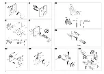
the steam generator, see fold-out page I, Fig. [1]. These vacant tubes 
are not included in the delivery specification.

• All cables must be pulled through using a pulling device to avoid damage.
• If there are more than four bends in a vacant tube, the cables must be 

pulled through the tube prior to installation.

• The enclosed 5m cable is suitable for vacant tubes up to 4.5m. 

The special accessory 47 837 can be used once per supply line for 
vacant tubes up to 9.5m.

• The device must be disconnected from the power supply prior to 

maintenance work.

Caution!

 Hot steam in the area around the steam outlet.

Steambath cubicle

The steambath cubicle must only be heated using the steam generator. 
The ambient temperature around the steambath cubicle and steam 
generator should not exceed 35 °C. If there is a sauna next to the 
steambath cubicle, it must be heat-insulated. There must be a minimum 
air gap of 100mm separating the walls of the sauna and the steambath 
cubicle.

Steam generator

Fitting and connection

, see fold-out page I, Fig. [2].

• The steam generator 

must

 be installed in a position high enough to 

ensure that the downward gradient of the outlet pipe leading to the 
waste water outlet is sufficiently steep. The steam generator must be 
mounted on the wall holders provided.

• The steam generator 

must

 be installed by an 

authorised electrician

The steam generator connections are permanent. The generator is 
installed outside the steam cubicle as close as possible to the control 
unit (a maximum of 5m away on the same floor or a maximum of 3m 
away on the floor above or below).

• The steam generator 

must

 be installed in a dry and ventilated room with 

a waste water outlet on the same floor as the steambath cubicle or one 
floor above or below. (Never install the generator directly above a waste 
water outlet or in an aggressive environment).

Pipe installation

The pipes 

must always

 be installed by a 

qualified installer

.

Water connection

, see fold-out page I, Fig. [3].

1.Select a pressure-reducing valve (A) or (A1) according to local and 

national regulations, see fold-out page I, Fig. [3].

2.Connect a water line with a minimum internal diameter of 12mm 

to the pressure-reducing valve (A)/(A1) and with a maximum water 
temperature at the inlet of 40 °C. Warm water accelerates the 
heating process.

3.Establish a connection between the pressure-reducing valve (A)/(A1) 

and steam generator using the hose provided (B).

Never reuse old hose sets!
IMPORTANT NOTE!

 Before connecting the water supply, carefully flush 

out the pipes to the steam generator (observe EN 806) to prevent metal 
chips or other foreign bodies from entering the steam generator lines.

Steam pipe installation

,


see fold-out page I, Fig. [4].

• Connect a copper pipe with a minimum inner diameter of 12mm 

(not included in the delivery specification) to steam outlet (C) on the 
connecting piece. The steam pipe leading to the steam generator 
must be perfectly horizontal.

IMPORTANT NOTE!

 The pipes between the steam generator and the 

steambath cubicle must not contain any "pockets of water" or bends 
where steam can condense and accumulate as water, see fold-out page I, 
Fig. [4].
The steam pipe should have as few bends as possible. The bends should 
curve gently and have a minimum radius of 50mm. The pipes must not 
contain any sharp kinks.

IMPORTANT NOTE! 

The flow rate inside the steam pipe must not be 

restricted (by a tap or valve). The inner diameter of the steam pipe must 
not be reduced in size in any way.
All steam lines must be insulated from end to end to protect against burns.

Floor, waste water outlet and ceiling

A waste water outlet designed to withstand the total flow rate of the 
consumer devices must be installed in the steambath cubicle. The floor 
must slope towards the waste water outlet. Suitable floor coverings 
include bonded plastic coverings, stone slabs, etc. The requirements for 
the consistency of the substrate, connections, etc. are the same as those 
of a shower cubicle. 

If a ceiling shower is to be installed in the steam 

bath cubicle, sufficient ventilation must be provided for the space 
above the ceiling shower. To avoid damage to the building structure, 
an additional coat of moisture-proof finish must be applied to all 
surfaces.
CAUTION!

 Plastic floor and wall materials located under the steam nozzle 

may change colour after coming into contact with steam and hot water.

Waste water outlet

Waste water outlet from steam generator

, see fold-out page I, Fig. [4].

1.Connect the outlet pipe (copper pipe with a minimum inner diameter 

of 12mm, not included in the delivery specification) to the connection 
(G½") on the steam generator.

2.Route the outlet pipe to the nearest waste water outlet outside the 

steambath cubicle. The temperature of the waste water is approx. 95 °C.

IMPORTANT NOTE! Shutting off the waste water pipe (e.g. with a tap 
or similar) is not permitted.

The outlet pipe from the steam generator to the waste water outlet must 
slope downwards regardless of the position of the waste water opening. 
The steam generator must be mounted on the wall holders provided.

This product conforms to the requirements of EU guidelines: 
2004/108/EC and 2006/95/EC

Please pass these instructions on to the fitting user!

The right to make technical modifications is reserved!

Summary of Contents for F-digital deluxe 27 934

Page 1: ...6 CN UA I 5 FIN 10 H 15 HR 20 RO 25 RUS 28 DESIGN ENGINEERING GROHE GERMANY www grohe com F DIGITAL DELUXE 93 950 131 M 231702 02 18 27 934 36 362 36 401 26 53 33 18 D 1 S GR GB DK CZ F N P E PL TR NL...

Page 2: ...II I 27 934 36 362 27 934 36 632 36 401 36 401 1 2 6 3 A A1 WRAS ACS 29mm 30mm 19mm B DVGW VA 4 5...

Page 3: ...III IV II 6 7 10 11 9 12mm 8 12 24mm 13 14 1 15...

Page 4: ...erden etwa durch einen Hahn oder ein Ventil Der Innendurchmesser des Dampfrohrs darf an keiner Stelle verkleinert werden Dampfbader ume die fortlaufend mehr als zwei Stunden in Betrieb sind m ssen ein...

Page 5: ...Abflussrohr z B durch H hne o sind unzul ssig Das Abflussrohr muss unabh ngig von der Position der Abflussm ndung vom Dampfgenerator bis zum Abfluss hin ein Gef lle aufweisen Dazu muss der Dampfgenera...

Page 6: ...and professional installation in combination with other modules Safety notes High temperatures occur Protect against burns Avoid danger due to damaged connection cables In the case of damage the conn...

Page 7: ...he same floor or a maximum of 3m away on the floor above or below The steam generator must be installed in a dry and ventilated room with a waste water outlet on the same floor as the steambath cubicl...

Page 8: ...ds outside An existing air duct can be used The duct must be completely steam and watertight and designed to withstand the high degree of moisture in the air Bends that allow the formation of pockets...

Page 9: ...rav que ce soit par un robinet ou une vanne Le diam tre int rieur du tuyau de vapeur ne doit se r duire aucun endroit Les bains de vapeur qui fonctionnent sans discontinuer durant plus de deux heures...

Page 10: ...dmis Le tuyau d vacuation doit tre inclin par rapport l vacuation quelle que soit la position de l orifice d vacuation du g n rateur de vapeur cet effet le g n rateur de vapeur doit tre mont sur le su...

Page 11: ...as Dichas instrucciones contienen informaci n importante para la instalaci n segura y profesional en combinaci n con otros m dulos Informaciones relativas a la seguridad Se producen altas temperaturas...

Page 12: ...omo m ximo en la misma planta y a 3m como m ximo en una planta inferior o superior El generador de vapor debe montarse en un espacio seco y ventilado dotado de desag e en una planta superior inferior...

Page 13: ...la alta humedad del aire No deben producirse dobleces en las que se formen bolsas de agua condensada ya que afectan negativamente al funcionamiento Si no es posible evitar una bolsa de agua deber ins...

Page 14: ...a Il diametro interno del tubo del vapore non deve essere rimpicciolito in nessun punto I bagni turchi che funzionano ininterrottamente per pi di due ore devono avere un ricambio d aria di 10 20m per...

Page 15: ...di scarico per es rubinetti o simili Indipendentemente dalla posizione dell imbocco dello scarico il tubo di scarico deve essere in pendenza nel tratto dal generatore di vapore allo scarico stesso A t...

Page 16: ...mer dell intervallo di decalcificazione secondo il manuale d istruzione dell applicazione di Grohe SPA NL Aanwijzing lees v r de installatie de complete montagehandleiding Deze bevat belangrijke infor...

Page 17: ...op dezelfde verdieping maximaal 5m een etage lager of hoger maximaal 3m De stoomgenerator moet in een droge en gevntileerde ruimte met een afvoer een etage boven onder of op dezelfde verdieping als d...

Page 18: ...ar de buitenlucht Een reeds aanwezige luchtschacht kan worden gebruikt De schacht moet volkomen stoom en waterdicht zijn en zodanig opgezet zijn dat deze bestand is tegen de hoge luchtvochtigheid Boch...

Page 19: ...exempel av en kran eller en ventil ngr rets innerdiameter f r inte f rminskas p n got st lle ngbadrum som anv nds mer n tv timmar i str ck m ste ha en luftv xling p 10 20m per person och timme Str mf...

Page 20: ...en lutning fr n nggeneratorn till avloppet oberoende av avloppsmynningens position F r detta ndam l m ste nggeneratorn monteras p den medf ljande v ggh llaren Montering av ngmunstycke se utvikningssid...

Page 21: ...deholder vigtige oplysninger om sikker og fagligt korrekt installation i forbindelse med yderligere moduler Sikkerhedsinformationer Der forekommer h je temperaturer Beskyt mod forbr ndinger Undg skade...

Page 22: ...ver et afl b eller i et aggressivt milj R rinstallation R rinstallationen m kun foretages af en autoriseret installat r Vandtilslutning se foldeside I ill 3 1 V lg reduktionsventil A eller A1 iht de n...

Page 23: ...iller til dr ning af kondensvandet Luftudgangen skal v re s stor at der kan bortledes 10 20m luft pr person og time Mekanisk udluftning Hvis det automatiske udtr k er utilstr kkeligt f eks ved undertr...

Page 24: ...ningen i dampr ret skal ikke v re hindret f eks av en kran eller ventil Dampr rets indre diameter skal ikke p noe sted v re innsnevret Dampbaderom som brukes mer enn to timer i strekk m ha en luftutsk...

Page 25: ...ran eller lignende Det skal v re et fall p avl psr ret fra dampgeneratoren til avl pet uavhengig av posisjonen til avl ps pningen Dampgeneratoren skal da monteres p den medf lgende veggholderen Monter...

Page 26: ...e SPA FIN Ohje Lue kiinnitysohjeet kokonaan ennen asennusta N iss on t rkeit tietoja varmaa ja ohjeenmukaista asennusta varten muiden yksik iden yhteyteen Turvallisuusohjeet L mp tilat nousevat korkei...

Page 27: ...h yrykaapin ulkopuolelle kuitenkin mahdollisimman l helle ohjausyksikk samassa kerroksessa enint n 5m kerrosta alempana tai ylemp n enint n 3m H yrygeneraattori pit asentaa kuivaan ja tuulettuvaan til...

Page 28: ...ilmakanavaa Kanavan pit olla t ysin h yry ja vesitiivis ja kestett v suurta ilmankosteutta Mutkia joihin muodostuu kondenssivesipusseja ei saa olla Jos vesipussia ei voi v ltt pit asentaa vedenerotin...

Page 29: ...zaw r W adnym miejscu wewn trzna rednica rury pary nie mo e by zmniejszona Wymiana powietrza w pomieszczeniach do k pieli parowych kt re stale pracuj przez ponad dwie godziny powinna wynosi 10 20m na...

Page 30: ...ezale nie od po o enia wyj cia odp ywowego z generatora pary W tym celu generator pary nale y zamontowa na za czonych uchwytach ciennych Monta dyszy pary zob strona rozk adana II rys 6 11 WA NE Przest...

Page 31: ...up ywem tego okresu Czas usuwania kamienia jest wy wietlany w panelu terminala Po up ywie czasu ustawionego na timerze zostaje zablokowany generator pary Spos b obs ugi aplikacji i aktywacji funkcji...

Page 32: ...29...

Page 33: ...30...

Page 34: ...2 230 V 1N AC 50 60Hz 2 2 kW CEE 7 7 40 C 5 dH 0 1 1 MPa A 1 2500 V 100 C GROHE Deutschland Vertriebs GmbH Zur Porta 9 D 32457 Porta Westfalica 700mm 10 20m 35 C 1500 1700mm 100 C 5 dH EN21 1 5m 4 5m...

Page 35: ...32 I 2 5m 3m I 3 1 A A1 I 3 2 40 C 12mm A A1 3 B A A1 EN 806 I 4 12mm C I 4 50mm I 4 1 12mm G 2 95 C II 6 11 50 400mm 700mm II 12 15 IEC 60364 7 701 VDE 0100 701 30 mA I 5 10 20m 1000mm...

Page 36: ...n m proveden kter je specifick pro r zn zem mus v m nu prov st elektroinstalat r s n le itou odbornou kvalifikac Je nutno db t na to aby elektrick ji t n bylo dimenzov no podle p konu parn ho gener to...

Page 37: ...biny s parn l zn av ak co nejbl e k ovl dac jednotce p i instalaci v t m e podla ve vzd lenosti max 5m p i instalaci o jedno podla n e nebo v e ve vzd lenosti max 3m Parn gener tor mus b t namontov n...

Page 38: ...o voln ho venkovn ho prostoru K tomuto elu m e b t pou ita st vaj c vzduchov achta achta mus b t dokonale parot sn a vodot sn a jej materi ly mus b t schopny sn et vysokou vlhkost vzduchu Nesm j se v...

Page 39: ...IGYELEM A g zvezet kben az raml st nem szabad akad lyozni p ld ul elz r csappal vagy szeleppel A g zvezet k bels tm r j t semmik ppen nem szabad lesz k teni A folyamatosan k t r n l hosszabb ideig zem...

Page 40: ...csonk helyzet t l f ggetlen l lejtenie kell a lefoly ir ny ba Ehhez a g zfejleszt t a mell kelt falitart ra kell szerelni A g zkif v felszerel se l sd a II kihajthat oldalon a 6 11 br kat FIGYELEM Ve...

Page 41: ...temperaturas elevadas Proteger contra queimaduras Evitar o perigo causado por um cabo de liga o danificado Em caso de danos o cabo de liga o tem de ser substitu do pelo fabricante pelo respectivo serv...

Page 42: ...mo piso no m ximo a 5m e num piso acima ou abaixo no m ximo a 3m O gerador de vapor deve ser montando num espa o seco e arejado com escoamento num piso acima abaixo ou no mesmo piso que a cabina de ba...

Page 43: ...onado para o ar livre Pode ser utilizado um po o de ar j existente O po o deve ser totalmente prova de gua e de vapor e deste modo suportar n veis elevados de humidade no ar N o devem existir ngulos n...

Page 44: ...rekli iki saatten uzun s re kullan lan buharl banyo mek nlar ki i ve saat ba na 10 20m l k bir hava al veri ine sahip olmal d r Buhar jenerat r ne giden ak m besleme hatt daima gerilim alt nda bulunm...

Page 45: ...a rn musluklar vs izin verilmez Gider borusu gider a z n n pozisyonundan ba ms z olarak gidere kadar bir e ime sahip olmal d r Bunun i in buhar jenerat r birlikte verilen duvar ask s na monte edilmeli...

Page 46: ...ciou si pre tajte kompletn mont ny n vod Tento n vod obsahuje d le it inform cie pre bezpe n a odborn in tal ciu v spojen s al mi modulmi Bezpe nostn inform cie Vyskytuj sa vysok teploty Chr te sa pre...

Page 47: ...i mimo kab ny parnej sauny pod a mo nosti o najbli ie k riadiacej jednotke na rovnakom podla maxim lne 5m o jedno poschodie ni ie alebo vy ie maxim lne 3m Parn gener tor sa mus namontova do such ho a...

Page 48: ...tuj ca vetracia achta achta mus by plne parotesn a vodotesn a zhotoven z materi lov schopn ch odol va vysokej vlhkosti vzduchu Nesm sa v nej vyskytova ohyby ktor vytv raj odvod ova e s kondenzovanou v...

Page 49: ...prek pipe ali ventila Notranjega premera parne cevi nikakor ne smete zmanj ati V prostorih s parnimi kopelmi ki delujejo e ve kot dve uri mora biti pretok zraka 10 20m na osebo v eni uri Elektri ni na...

Page 50: ...ka mora odto na cev potekati pod naklonom ne glede na lego odto ne odprtine Poleg tega morate generator pare namestiti na prilo eno stensko dr alo Monta a obe za paro glejte slike od 6 do 11 na zlo lj...

Page 51: ...mna v skladu z navodili za uporabo aplikacije Grohe SPA ponovno nastavite HR Napomena Prije ugradnje pro itajte u cijelosti upute za monta u Upute sadr e va ne informacije o sigurnoj i stru noj ugradn...

Page 52: ...o priklju en Postavlja se izvan parne tu kabine ali to je mogu e bli e upravlja koj jedinici na istom katu maksimalno 5m na eta i ispod ili iznad maksimalno 3m Parni generator mora se montirati u suho...

Page 53: ...o e se koristiti ve postoje e ventilacijsko okno Okno mora biti potpuno nepropusno za paru i vodu i tako konstruirano da podnosi veliku vla nost zraka Ne smije dolaziti do savijanja na kojima se skupl...

Page 54: ...230 V 1N AC 50 60 Hz 2 2 kW CEE 7 7 40 C 5 dH 0 1 1 MPa A 1 2500 V 100 C GROHE Deutschland Vertriebs GmbH Zur Porta 9 D 32457 Porta Westfalica 700mm 10 20m 35 C 1500 1700mm 100 C 5 dH EN21 1 5m 4 5m...

Page 55: ...52 I 2 5m 3m I 3 1 A A1 I 3 2 40 C 12mm A A1 3 B A A1 EN 806 I 4 12mm C I 4 50mm I 4 1 12mm G 2 95 C II 6 11 50 400mm 700mm II 12 15 IEC 60364 7 701 VDE 0100 701 30 mA I 5 10 20m 1000mm 10 20m 10m 20m...

Page 56: ...lmas et elektriliste kaitsete puhul on arvesse v etud aurugeneraatori tarbitavat v imsust Pistik hendust ei tohi puhastamisel vahetult ega kaudselt veega m rjaks pritsida Toitepinge peab olema kesksel...

Page 57: ...alt oma kohale See paigaldatakse aurusauna kabiinist v ljapoole kuid juhtimisseadmele v imalikult l hedale samal korrusel maksimaalselt 5m kaugusele ks korrus les v i allapoole maksimaalselt 3m kaugus...

Page 58: ...Kasutada v ib juba olemasolevat ventilatsioonitoru Toru peab olema t ielikult auru ja veekindel ja selle konstruktsioon peab taluma k rget huniiskust Paindeid kuhu saab toimimist m jutav kondenseeritu...

Page 59: ...Nevien viet nedr kst tikt samazin ts tvaika caurules iek jais diametrs Tvaika vannas istab s ko izmanto ilg k par div m stund m ir j veic gaisa apmai a 10 20m vienai personai stund Elektroapg des pad...

Page 60: ...mus piem ram kr nu rad tus Neatkar gi no noteces atveres vietas noteces caurulei j veido notece no tvaika eneratora T d tvaika eneratoram ir j pievieno pieg des komplekt iek autie sienas turek i Tvaik...

Page 61: ...strukcijoje pateikta svarbi informacija apie saug ir tinkam rengim derinant su kitais moduliais Saugos informacija Susidaro auk ta temperat ra Saugokit s nudegim B kite atsarg s pa eisti prijungimo la...

Page 62: ...ies kabinos bet kuo ar iau valdymo bloko tame pa iame auk te daugiausia 5 m atstumu vienu auk tu emiau arba auk iau daugiausia 3 m atstumu Gar generatorius turi b ti sumontuotas sausoje ir v dinamoje...

Page 63: ...ama prie oro achtos vedan ios lauk Galima naudoti jau esam oro acht achta turi b ti nepralaidi garams ir vandeniui bei atspari didelei oro dr gmei Neturi b ti u lenkim kuriuose susidaro kondensato mai...

Page 64: ...rat n locurile mai str mte Spa iile cu baie de abur care au fost n func iune peste dou ore n continuu trebuie s dispun de o schimbare a aerului de 10 20m de persoan pe or Cablul de alimentare cu curen...

Page 65: ...cu robinete etc eava de evacuare trebuie s aib o pant descendent de la generator de abur la evacuare indiferent de pozi ia gurii de evacuare Pentru aceasta generatorul de abur trebuie s fie montat pe...

Page 66: ...lui terminal C nd valoarea de pe cronometru a expirat generatorul de abur se blocheaz Procedura pentru utilizarea aplica iei i activarea func iilor trebuie s fie desc rcat din alte instruc iuni de la...

Page 67: ...d Vertriebs GmbH Zur Porta 9 D 32457 Porta Westfalica 700 10 20 35 C 1500 1700 100 C 5 dH EN21 I 1 5 4 5 47 837 9 5 35 C 100 I 2 5 3 I 3 1 A A1 I 3 2 12 A A1 40 C 3 B A A1 EN 806 I 4 12 C I 4 50 I 4 1...

Page 68: ...65 II 6 11 50 400 700 II 12 15 IEC 60364 7 701 VDE 0100 701 FI 30 I 5 10 20 1000 10 20 10 20 110 130 130 www grohe com tpi f digital deluxe 1 20 2 3 80 g 14 015 000 4 1 5 5 Grohe SPA...

Page 69: ...60309 36 362 230 1 50 60 2 2 CEE 7 7 40 C 5 dH 0 1 1 A 1 2500 100 C GROHE Deutschland Vertriebs GmbH Zur Porta 9 D 32457 Porta Westfalica 700 10 20m 35 C 1500 1700 100 C 5 dH EN21 I 1 5 4 5 9 5 47 83...

Page 70: ...67 5 3 3 1 A A1 I 3 2 A A1 40 C 12 3 A A1 EN 806 I 4 12 I 4 50 I 4 1 12 G 2 95 C 6 11 50 400 700 12 15 IEC 60364 7 701 VDE 0100 701 30 I 5 10 20m 1000 10 20 10 20...

Page 71: ...deluxe 1 20 2 3 80 14 015 000 4 1 5 5 Grohe SPA RUS 27 934 6 6 CEE IEC 60309 36 362 2 2 CEE 7 7 27 934 400 3N 50 60 6 6 CEE IEC 60309 36 362 230 1N 50 60 2 2 CEE 7 7 40 C 5 dH 0 1 1 3 Elys e Excellent...

Page 72: ...d Vertriebs GmbH Zur Porta 9 D 32457 Porta Westfalica 700 10 20 35 C 1500 1700 100 C 5 dH EN21 I 1 5 4 5 9 5 47 837 35 C 100 I 2 5 3 I 3 1 A A1 I 3 2 A A1 40 C 12 3 A A1 B EN 806 I 4 12 I 4 50 I 4 1 1...

Page 73: ...70 II 6 11 50 400 700 II 12 15 IEC 60364 7 701 VDE 0100 701 30 I 5 10 20 1000 10 20 10 20 110 130 130 www grohe com tpi f digital deluxe 1 20 2 3 80 14 015 000 4 1 5 5 Grohe SPA...

Page 74: ...Grohe AG 27 934 36 362 36 401 X X X X X X X X X X X X X X X X X X 15 5 15 5 17 3...

Page 75: ......

Page 76: ...727 311 07 39 info cac grohe com LT 372 6616354 grohe grohe ee LV 372 6616354 grohe grohe ee MAL 1 800 80 6570 info singapore grohe com MX 01800 8391200 pregunta grohe com N 47 22 072070 grohe grohe n...

Reviews: