22
21
L1
→
LINE 1 (Black)
L2
→
LINE 2 (Grey)
L
→
LINE 3 (Brown)
→
Ground (Yellow-Green)
N
→
Neutral (Blue)
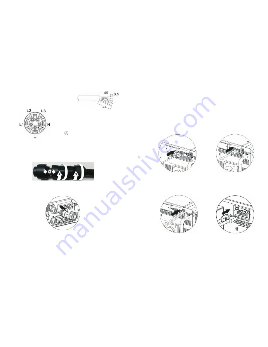
Step 4: Push protective dome (D) on to socket element (E) until both are locked
tightly. Then, twist protective element (D) and pressure dome (A) so that all cables are
firmly connected.
Step 5: Plug the socket into the terminal.
Step 3: Thread five cables through socket
element (E) according to polarities indicated on
it and tighten the screws to fix wires after
connection.
CAUTION:
connect the utility to “AC Output Connector”.
CAUTION: Be sure to connect L terminal of load to L terminal of “AC Output
Connector” and N terminal of load to N terminal of “AC Output Connector”. The G
terminal of “AC Output Connector” is connected to grounding of the load. Do NOT
mis-connect.
It’s only allowed to connect load to “AC Output Connector”. Do NOT
Communication
9
The inverter is equipped with several communication ports and it is also equipped
with a slot for alternative communication interfaces in order to communicate with a
PC with corresponding software. This intelligent slot is suitable to install with SNMP
card and Modbus card. Follow below procedure to connect communication wiring
and install the software.
For RS232 port, you should use a
DB9 cable as follows:
For USB port, you should use a
USB cable as follows:
For Dry contact port, please
remove insulation sleeve 8 mm for
three conductors and insert three
cables into ports
For SNMP or MODBUS card, you
should use RJ45 cables as follows:
Please install monitoring software in your computer. Detailed information is listed in
the next chapter. After software is installed, you may initial the monitoring software
and extract data through communication port.
Figure 8.2
Figure 8.3
Figure 8.4
Figure 8.5
Figure 9.1


