background image

14

13

5.2 Selecting the installation location

Ø

This is guidance for installer to choose a suitable installation location, to avoid 

potential damages to device and operators. 

Ø

The installation location must be suitable for the inverter's weight and 

dimensions for a long period time.

Ø

Select the installation location so that the status display can be easily viewed.

Ø

Do not install the inverter on structures constructed of flammable or thermolabile 

materials.

Ø

Never install the inverter in environment of little or no air flow, nor dust 
environment. That may derate the efficiency of the cooling fan of the inverter.

Ø

The Ingress Protection rate is IP65 which means the inverter can be installed 
outdoors and indoors.

Ø

The humidity of the installation location should be 0~100% without condensation.

Ø

The installation location must be freely and safely to get at all times.

Ø

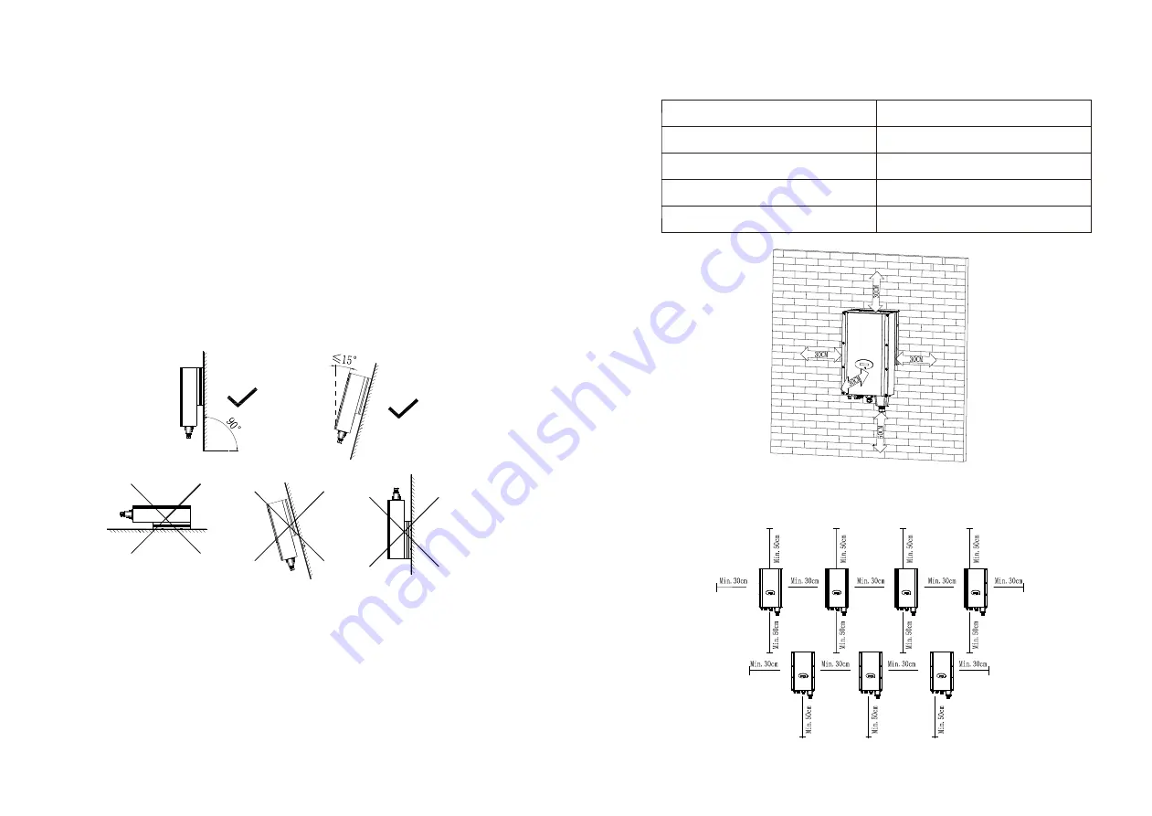
Vertically installation and make sure the connection of inverter must be 

downwards. Never install horizontal and avoids forward and sideways tilt.

Ø

Be sure that the inverter is out of the children's reach.

Ø

Don't put any things on the inverter. Do not cover the inverter.

Ø

Do not install the inverter near television antenna or any other antennas and 

antenna cables.

Ø

Inverter requires adequate cooling space. Providing better ventilation for the 
inverter to ensure the heat escape adequately. The ambient temperature should 
be below 40°C to ensure optimum operation. 

Ø

Do not expose the inverter to direct sunlight, as this can cause excessive heating 
and thus power reduction.

Ø

Observe the Min. clearances to walls, other inverters, or objects as shown in the 

diagram:

Direction

above

below

sides

front

Min. clearance (cm)

30

30

30

50

Ambient dimensions of one inverter

Ambient dimensions of series inverters

Summary of Contents for 10500MTLP-S

Page 1: ...ict Shenzhen P R China No 28 Guangming Road Shiyan Street Bao an District Shenzhen P R China GR UM 157 A 00 86 0755 2747 1942 86 0755 2747 1942 www ginverter com www ginverter com T E W service ginver...

Page 2: ...ion of skilled person 2 3 Safety instruction 2 4 Assembly Warnings 2 5 Electrical Connection Warnings 2 6 Operation Warnings 1 1 Validity 1 2 Target Group 1 3 Additional information 1 4 Symbols in thi...

Page 3: ...tion 13 2 DC connector info 13 3 Torque 13 4 Accessories 6 Electrical connection 12 Decommissioning 7 Commissioning 13 Technical Data 14 PV system installation 7 1 LCD display 7 2 Setting the LCD disp...

Page 4: ...the Growatt equipment or personal injury This manual describes the assembly installation commissioning and maintenance of the following Growatt Inverter model Growatt 8000MTLP S Growatt 9000MTLP S Gr...

Page 5: ...d safety rules Nevertheless improper use may cause lethal hazards for the operator or third parties or may result in damage to the units and other property Principle of a PV plant with thisGROWATT XXX...

Page 6: ...ay from children There is residual voltage in the inverter The inverter takes 20 minutes to ischarge The components in the inverter are live Touching live components can result in serious injury or de...

Page 7: ...standardized emission limit values e g when sensitive equipment is located at the setup location or when the setup location is near radio or television receivers In this case the operator is obliged t...

Page 8: ...age local installer or service department of GROWATT should perform a comprehensive test before installation Maximum efficiency of 98 1 Wide input voltage range from 100 600Vdc Reactive power regulate...

Page 9: ...nal PV PV metal terminal RS485 Waterproof cover AC Waterproof cover All electrical installations shall be done in accordance with the local and national electrical codes Do not remove the casing Inver...

Page 10: ...condensation The installation location must be freely and safely to get at all times Vertically installation and make sure the connection of inverter must be downwards Never install horizontal and avo...

Page 11: ...nstalled at the right place The inverter can t install close to trunk Information General tools 1 Personal safety equipment such as gloves helmet goggles ear plugs safety harness etc 2 Step ladders 3...

Page 12: ...he inverter on the bracket unless you are sure that the mounting frame is really firmly mounted on the wall after carefully checking WARNING WARNING WARNING Using the mounting frame as a template dril...

Page 13: ...esidual current you must choose a AC breaker with the rating residual current more than 300mA We suggest you choice the AC breaker rating current in this table we recommend electrical connection as fo...

Page 14: ...ut don t have to screw it completely as shown below 2 Plugging the connected wire RS485 terminal into the RS485 terminal of the inverter as shown below 3 Lock the RS waterproof cover to the inverter c...

Page 15: ...phase inverter has three independent MPPT A B and C the MPPT A has two independent PV array inputs MPPT B and MPPT C have one PV array input the corresponding terminal block is shown below 2 The PV c...

Page 16: ...er can be controlled by knocking on the front of it The first line will show some status of the inverter there are 4 status listed in below table Inverter State Fault State Program State DISPLAY CONTE...

Page 17: ...ws 2324 5W 16 7Var AC Error Record 1 NO AC 2018 10 15 08 21 2 AC F out range 2018 12 05 11 21 5 AC V out range 2018 10 15 08 21 4 NO AC 2018 11 08 12 21 3 NO AC 2018 11 05 17 31 Single knock Single kn...

Page 18: ...to the inverter data by accessing the sever More details can be found in the Wifi module manual 1 Connect the AC breaker of the inverter 2 Turn on the dc switch and the inverter will start automatical...

Page 19: ...ity grid voltage or frequency change frequently 10 2 Warnings W Warnings W identify the current status of the Growatt 8 10K MTLP S inverter Warnings do not relate to a fault When a W with a number aft...

Page 20: ...er with household waste Please accordance with the disposal regulations for electronic waste which apply at the installation site at that time Ensure that the old unit and where applicable any accesso...

Page 21: ...Certificatesand approvals INMETRO IEC61727 62116 Interfaces RS485 RF WiFi GPRS yes opt opt opt 13 2 DC connector info 13 3 Torque DC connector Enclosure lid screws Shell and RS232 screws AC terminal...

Page 22: ...he appropriate settings the unit will comply with the requirements specified in the following standards and directives dated December 2018 INMETRO IEC61727 62116 GROWATT can preset special grid parame...

Page 23: ...cessary assistance Inverter type Serial number of the inverter Event number or display message of the inverter Type and number of PV modules connected Optional equipment GROWATT NEW ENERGY TECHNOLOGY...

Reviews: