background image

15

16

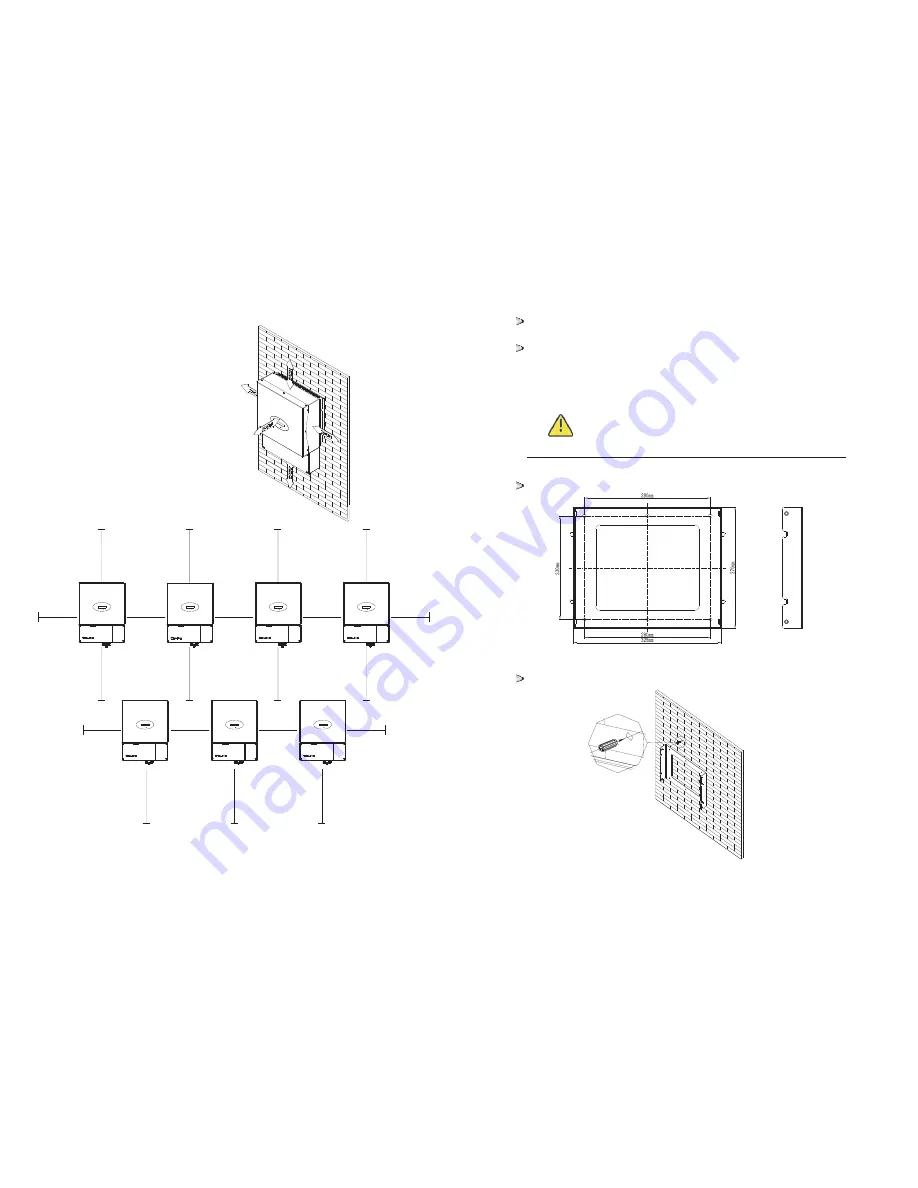
There must be sufficient clearance between the individual inverters to

ensure that the cooling air of the adjacent inverter is not taken in.

If necessary, increase the clearance spaces and make sure there is enough

fresh air supply to ensure sufficient cooling of the inverters.

5.3 Mounting the Inverter with bracket

WARNING

In order to avoid electrical shock or other injury, inspect

existing electronic or plumbing installations before

drilling holes.

The dimension of bracket as follow

Using the mounting frame as a template, drill holes as illustrated in

image.

Ambient dimensions of one inverter

Ambient dimensions of a series inverters

M

in 30cm

.

Min.50cm

M

in 30cm

.

M

in 30cm

.

M

in 30cm

.

M

in 30cm

.

M

in 30cm

.

M

in 30cm

.

M

in 30cm

.

M

in 30cm

.

Min.50cm

Min.50cm

Min.50cm

Min.50cm

Min.50cm

Min.50cm

Min.50cm

Min.50cm

Min.50cm

Min.50cm

Summary of Contents for 1500-US

Page 1: ...Installation Operation Manual...

Page 2: ...scription 3 1 Inverter Overview 3 2 Information of Label 3 3 Dimensions and weight 3 4 Transportation 3 5 Storage of Inverter Directory 1 2 3 4 1 Unpacking and inspection 1 4 Storage of the manuals 1...

Page 3: ...e connection 7 4 Using shine tool to set the information of the inverter 8 1 Start Up the inverter 8 2 Disconnecting the Inverter 9 1 Checking Heat Dissipation 9 2 Cleaning the Inverter 9 3 Checking t...

Page 4: ...ion and operation of this device Qualified personnel are trained to deal with the dangers and hazards involved in installing electric devices 1 4 Storage of the manuals The manual and other documents...

Page 5: ...he unit Even when the unit is disconnected high contact voltages may still be present within the unit DANGER DANGER Danger of burn injuries due to hot enclosure parts During operation the four sides o...

Page 6: ...nging software parameters with respective communication products e g shinebus or shineNet ect To change the grid relevant parameters you need a personal access code if you need it please contact with...

Page 7: ...1 Phase Inverter Range of input voltage 100 450Vdc Max input short circuit current 15Adc Norminal output power 1650W Range of grid voltage 183 228Vac 208Vac Range of grid frequency 59 3 60 5Hz Normina...

Page 8: ...iciency of 96 Growatt 2000 US Growatt 3000 US CEC efficiency of 96 5 Integrated wire box Integrated DC switch High MPP efficiency of 99 5 Adapt to multi gird model 208Vac 240Vac 277Vac Sound control E...

Page 9: ...her source of energy to it Both AC and DC voltage sources are terminated inside the PV Inverter Please disconnect these circuits before servicing This unit is designed to feed power to the public powe...

Page 10: ...or tilted backwards by max 15 and make sure the connection of inverter must be downwards Never install horizontal and avoids forward and sideways tilt Be sure that the inverter is out of the children...

Page 11: ...h bracket WARNING In order to avoid electrical shock or other injury inspect existing electronic or plumbing installations before drilling holes The dimension of bracket as follow Using the mounting f...

Page 12: ...cket After confirming the inverter is fixed reliably fasten four M6 safety lock sokets head cap screws on the left and right side firmly to prevent the inverter from being lifted off the bracket 5 5 C...

Page 13: ...Connection PV Panel Provide DC power to inverter Converts DC Direct Current power from PV panel to AC Alternating Current power Because Inverter is grid connected it controls the current amplitude ac...

Page 14: ...he local grid standards it is possible to select different connection types The available configurations are shown in the following table NOTE in the inverter wire box AC terminal pin is written as L1...

Page 15: ...he knock out hole and pull the pipe nut slightly feed the cables through the pipe into the wire box till the terminal 2 Open the wire box cover and the knock out hole We suggest the AC separate unit s...

Page 16: ...system are normally ungrounded but will become intermittently grounded without indication when the inverter measures the PV array isolation Because of the transformer less design the DC positive pole...

Page 17: ...exist when the PV panel is exposed to the sun To reduce risk of electric shock avoid touching live components and treat connection terminals carefully 1 Open the independent DC separate unit the DC sw...

Page 18: ...e ratio of true power or watts to apparent power or volt amps They are identical only when current and voltage are in phase than the power factor is 1 0 The power in an ac circuit is very seldom equal...

Page 19: ...er model 2 2 2 The software version The Serial Number 4 The energy today 4 The energy all 4 PV input watt 4 The PV and Bus Votage The grid system 4 Set Language 4 Set LCD Contrast 4 Set Communications...

Page 20: ...he Address model clock to set address Setting grid model choice This function is disable when the inverter work in the normal state you much turn off the AC separate unit and the inverter LCD will dis...

Page 21: ...unication ShineWebbox can simultaneously monitor record and analyze inverter operating parameters real time with a maximum quantity of 50 Monitored data also can be sent to Shine Server Shine Pano 7 1...

Page 22: ...RS485 232 converter PC 7 3 RS485 cable connection 1 Unscrew the plastic connector 2 Make the RS485 cable go through the connector 3 Put two heat shrink tubes onto the front head of RS485 cable 4 Inser...

Page 23: ...atically when the input voltage is higher than 150V 8 2 Disconnecting the Inverter 1 Disconnect the AC circuit breaker and prevent it from being reactivated 2 Turn off the dc switch 3 Check the invert...

Page 24: ...0 minutes before disassembling until the housing has cooled down 3 Screw off all projecting cable glands 4 Lift the inverter off the bracket and unscrew the bracket screws 10 2 Packing the Inverter If...

Page 25: ...rowatt Output High DCI Output current DC offset too high 1 Restart inverter 2 If error message still exists contact Growatt Residual I High Leakage current too high 1 Restart inverter 2 If error messa...

Page 26: ...o low the inverter will also turn to Shutdown Mode De rating Operation 13 De rating Operation 13 Temperature The inverter will monitor the temperature of the heat sink Once the temperature exceeds 75...

Page 27: ...e surges lighting flood fire exposure to incorrect use negligence accident force majeure explosion terrorist act vandalism or damage caused by incorrect installation modification or extreme weather co...

Page 28: ...240 277V ac Max output current 8A 7 8A 6 8A 9 7A 9 4A 8 2A 15A 14 2A 12 3A AC grid frequency range 60Hz 59 3 60 5Hz 60Hz 59 3 60 5Hz 60Hz 59 3 60 5Hz Efficiency Max efficiency 97 97 97 CEC efficiency...

Page 29: ...display LCD LCD LCD Interfaces RS485 RS232 Bluetooth RF Zigbee yes yes opt opt opt yes yes opt opt opt yes yes opt opt opt Warranty 10 years 15 years yes opt yes opt yes opt Certificates and approval...

Page 30: ...hnical problems about our products contact the Growatt Service line We need the following information in order to provide you with the necessary assistance Inverter type Serial number of the inverter...

Reviews: