background image


25 

Troubleshooting 

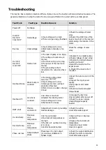
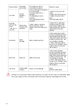
The inverter has complete protection. When a failure occurs, the inverter will take protective measures. The 
general protection is to stop the motor from running and forbid it to restart within a certain period.  
 

Fault Code 

Fault type 

Possible Reasons 

Solution 

Power off 

No failure  

Inc OVP 
Dec OVP  

Const OVP 

Overvoltage 

1.Input voltage is too high 
2.There is large energy feedback 

1.Check the voltage of solar 
array  

2.Check if the DEC time of the 
load is too short or the inverter 
starts during the rotation of the 

motor 

Bus low 

Undervoltage 

1.Input voltage is too low; 
2.Illumination intensity is too 
weak 

Check the voltage of solar 

array 

Inc  OCP 
Dec OCP  

const OCP 

Overcurrent 

1.The load of pump is too large; 

2.The voltage of solar array is 
too low; 

3.The motor wiring is too long 
4.The power of the inverter is 

too low 
5.The grounding is short 
circuited or the output is phase 

loss 

1.Replace for a smaller pump; 
2.Check voltage of solar array; 

3.Shorten the wiring between 
inverter and motor 
4.Select the inverter with a 

larger power 
5. Check if the load is short 

circuited


Overload Pump 

Water pump is 
overload  

1.The motor setting rated 
current is 

incorrect


2.Input voltage is too low 
3.Improper motor’s overload 

protection threshold 
4.Motor block or sudden  change 

of load 

1.Reset the rated 

current 

of the 

motor 
2.Inspect the input power 

supply 
3.Set proper motor rated 
current 

4.Check the load and adjust 
torque boost 

Overload VF 

Inverter is 

overload 

1.Acc time is too short 
2.Restart the rotating motor 

3.Input voltage is too low 
4.the load is too heavy 

1.Increase the Acc time 
2.Avoid restart after power off 

3.Check the power supply 
4.Select bigger capacity 

inverter 

IGBT short 

Module 
overcurrent 

Output short circuit or grounding 
module damage 

1.Check the wiring  
2.Get after-sells support 

Inv Overtemp 

Module is 
over-

temperature  

1.Air flue is blocked 

2.Environment temperature is 
too high 

3.The time of  overload running 
is too long. 
4.Control board abnormal 

1.Clean air flue or improve 

ventilation 
2.Degree the environment 

temperature 
3.Select a proper motor 
4.Ask for support 

Rec Overtemp 

Module is 
over-

temperature 

Phase out loss 

Output default 
phase  

Phase loss of U,V,W output 
(or a serious unbalance in 

3phase input) 

1.Check the output distribution 
2.Check the motor and cable 

3.Get after-sells support 

Summary of Contents for 1500TL2-HV

Page 1: ...Solar Pump Inverter 750W 4000W Version 1 3 User Manual...

Page 2: ...it 5 Wiring Introduction 7 Terminal Introduction 7 Assemble DC Connector 8 Assemble AC Output Connector 8 Assemble AC Input Connector 10 Assemble sensor Connector 11 Wiring of Water Level Sensor 12 Re...

Page 3: ...h this document and all safety information Safety Instructions WARNING This chapter contains important safety and operating instructions Read and keep this manual for future reference Inspection If mi...

Page 4: ...res of them 3 When testing water pump be sure to install water pump at appropriate water level Never allow water pump in dry running Otherwise the inverter will activate protection Maintenance 1 Only...

Page 5: ...to set the priority of PV and utility grid input The inverter is suitable for submersible pumps ground pumps swimming pool pumps and other pumps using asynchronous motors Features Rated power 750W to...

Page 6: ...4 Product Overview 1 LCD display 2 LED indicators 3 Function buttons 4 AC input 5 PV input 6 Water level sensor port 7 AC output 8 GPRS WIFI communication port...

Page 7: ...t on a solid metal surface Avoid direct sunlight Be sure the environment is shadyand cool Be sure to install the inverter into a box with waterproofand dustproof Install this inverter at eye level in...

Page 8: ...6...

Page 9: ...AC Output 3 PH motor connect 1 2 L 1 PH motor connect 1 L 1 Connect with motor U phase 2 Connect with motor V phase L Connect with motor W phase PE Connect with protective ground wire COM terminal 1...

Page 10: ...iring Warning Risk of electric shock Before shifting solar panel disconnect the pump inverter AC and DC Besides allow 5 minute internal capacitance discharging Assemble AC Output Connector Connection...

Page 11: ...screw Insert the stripped and bared conductors U V W PE in to screw terminals with sign U V W PE on the socket element and tighten the screws Connect the conductors Push the threaded sleeve in to the...

Page 12: ...pressure screw Insert the stripped and bared conductors L N PE in to screw terminals with sign L N PE on the socket element and tighten the screws Connect the conductors Push the threaded sleeve in to...

Page 13: ...well 7 8 Insert the stripped and bared cable through pressure screw sealing threaded sleeve in sequence insert cables into connection terminal according to number indicates on it and tighten the screw...

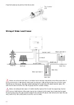
Page 14: ...level recovers Wait for 20s then the pump inverter re works normally Notice connect water level sensor 2 to defect whether water is full Connect two signal lines of sensor with 1 and 2 of COM termina...

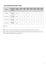
Page 15: ...4 4 6 1500TL2 HV 7 5A 3PH 10 2A 1PH 220V 1 5 2 5 2 5 6 6 6 6 2200TL2 HV 10A 3PH 14 1PH 220V 2 5 2 5 4 6 6 6 6 4000TL2 HV 16A 3PH 25 1PH 220V 4 4 6 8 8 8 8 Units mm2 Notice The environment temperature...

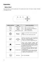
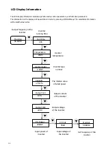
Page 16: ...ps control Confirm Programming Key 1 Press for a short time to enter programming mode After altering parameter press for a short time to confirm the alteration 2 Press for 2s to enter the programming...

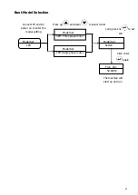
Page 17: ...enter the model setting Click enter again Model Set 3PH Three plase motor Model Set 1PH Single phase motor Long press 3s to set OK Press up and down to select motor type Model Set Set OK Freq Run 50...

Page 18: ...as below Inverter temperature Freq Run 50 00HZ Output frequency of the inverter Freq Set 50 00HZ Set frequency of the inverter PV Volt 350V Input voltage of the inverter PV Power 2000W Input power of...

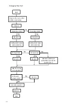
Page 19: ...alue d Water output test of pump Click the run button to observe the running frequency and water output Under the normal strong light condition if the operation frequency of three phase motor is low o...

Page 20: ...P02 00 0 Setting motor name plate parameters Setting motor name plate parameters P15 29 2 P15 29 1 Automatic switching of photovoltaic input and AC input P15 29 0 Click the run key on the keyboard P00...

Page 21: ...terminal work mode Press the enter key again Change the default value of 1 to 0 Work mode P00 Enter the main parameter modification interface for long press 2s for Enter key Work mode P00 01 Press Ent...

Page 22: ...ed all group parameters will return to the default settings except for group P02 Click enter to set OK to return Power off Long press for 3 seconds to shut down Work mode P00 Enter the main parameter...

Page 23: ...eted return to the main page and press the 3s shutdown key for shut down Power off Work mode P00 Enter the main parameter modification interface for long press 2s for Enter key Model set P02 00 Turn u...

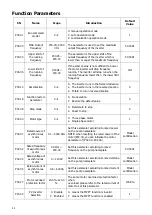
Page 24: ...peration 1 Restore the default value 0 P01 08 Stop mode 0 1 0 Decelerate to stop 1 Coast to stop 0 P02 00 Motor type 0 1 0 Three phase motor 1 Single phase motor 1 P02 01 Rated power of asynchronous m...

Page 25: ...n or equal P15 19 and the current corresponding to the current frequency is less than P15 17 after the time set by P15 16 the inverter will stop run otherwise it will operate normally If the state is...

Page 26: ...n the threshold or the light is weak it can be switched to power frequency input through relay output Note The minimum operation voltage of the system is 60V If the value is 0 the function is disabled...

Page 27: ...load is short circuited Overload Pump Water pump is overload 1 The motor setting rated current is incorrect 2 Input voltage is too low 3 Improper motor s overload protection threshold 4 Motor block o...

Page 28: ...y Lack Water Water shortage Water shortage warning 1 If the water empty alarm function is enabled the device automatically stops after the water empty alarm remains for a certain period of time and no...

Page 29: ...1PH 10A 3PH 14 1PH 16A 3PH 25 1PH Output wiring mode 1P2L 3P3L Output voltage 0 220V Output frequency 0 50 60Hz CONTROL PERFORMANCE Control mode V F Motor type Asynchronous motor 1 Phase 220V 3 Phase...

Reviews: