26
27
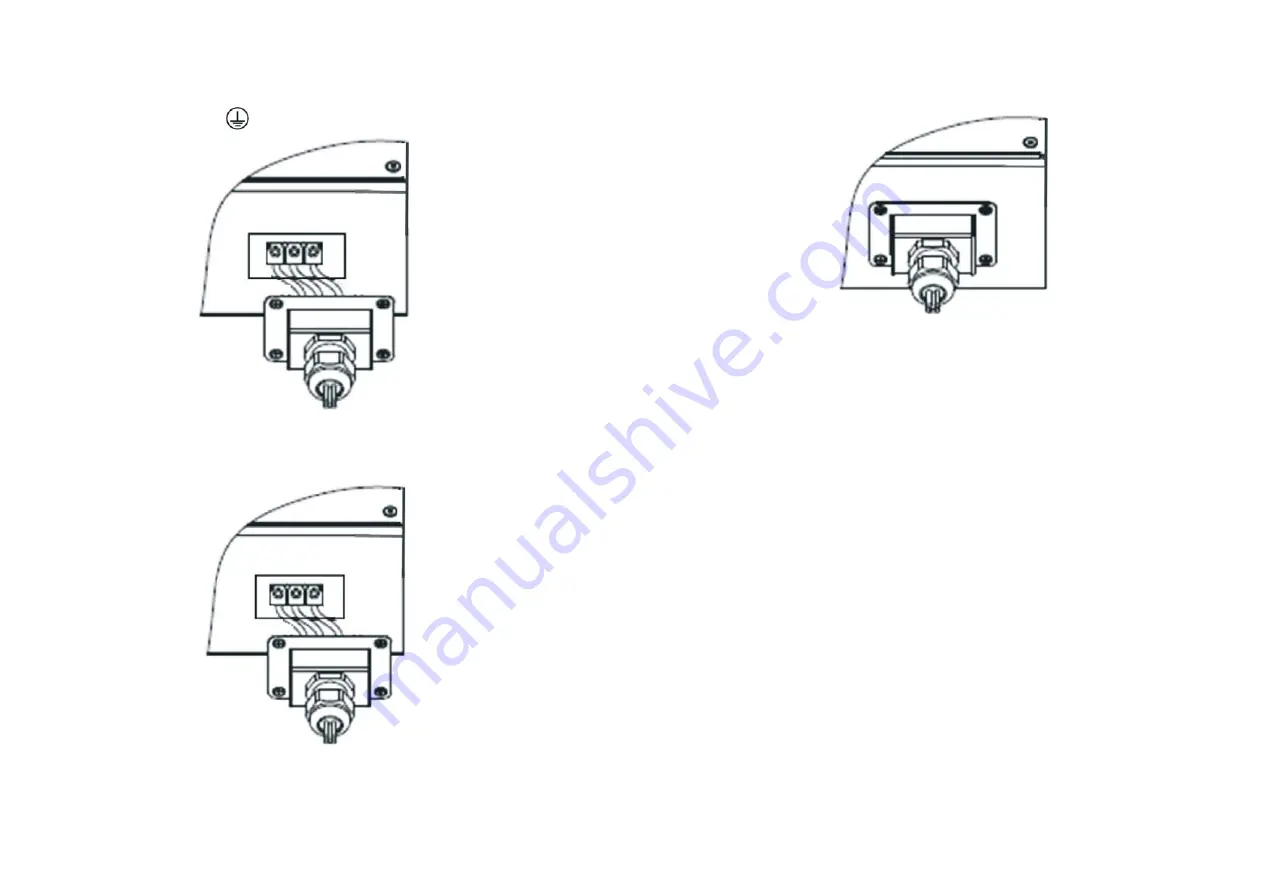
1.The AC side terminals of the inverter are like the following figure, it is clear to
confirm that 'L' represents live line output, 'N' represents null line output, 'N'
represents null line and
is grounding line.
2.Connect three standard cables into relevant terminals. The three cables should be
put through the protection shell, as figure below.
3.Fasten the protection shell onto the bottom of the inverter, make sure the four
screws are tightened, the completed appearance is like the below figure
Cable requirements:
Model
_(mm)
AWG no.
Growatt2500MTL
_2.05
3.332
12
Growatt 3000MTL
_2.05
3.332
12
Growatt3600MTL
_2.59
5.260
10
Growatt 4200MTL
_2.59
5.260
10
Growatt 4600MTL
_2.59
5.260
10
Growatt 5000MTL
_2.59
5.260
10
5.7.3. Connecting the PV array
5.7.3.1. Conditions for DC connection
The inverter has 2 independent input : input A & input B
The diagram drawing of DC side is shown as below, notice that the connectors are in
paired (male and female connectors). The connectors for PV arrays and inverters are
H4 (AMPHENOL) connectors;
Area(mm )
2
MAX.cable
length(m)
30
25
33
29
26
24


