26
25
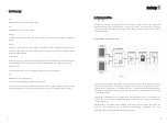
Connection to the AC side terminal
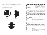
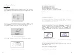
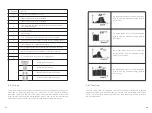
The AC side terminals of the inverter are like the following figure, it is clear to
confirm that ‘L1, L2, L3’ represents three live line output, ‘N’ represents neutral line
and is grounding line.
Connect five standard cables into relevant terminals. The five cables should be put
through the protection shell, as figure below.
N
L1
L2
L3
N
L1
L2
L3
Fig5
.
11
Fig 5
.
10
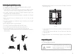
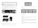
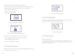
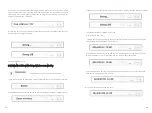
Fasten the protection shell onto the bottom of the inverter, make sure the four
screws are tightened, the completed appearance is like the below figure
Fig 5
.
12
5.4.3 Wiring DC Input
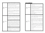
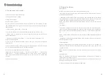
Danger to life due to lethal voltages!
Before connecting the PV array, ensure that
the DC switch and AC breaker are disconnect
f ro m t h e i n v e r t e r. N E V E R c o n n e c t o r
disconnect the DC connectors under load.
Improper operation during the wiring process can cause
fatal injury to operator or unrecoverable damage to the
inverter. Only qualified personnel can perform the
wiring work.
Risk of damage to the inverter.
If the voltage of the PV modules exceeds the maximum
input voltage of the inverter, it can be destroyed by the
overvoltage. This will void all warranty claims.
Do not connect strings to the inverter that have an
open-circuit voltage greater than the maximum input
voltage of the inverter.
To reduce the risk of electric shock, avoid touching the
live components and treat the terminals carefully.
The PV modules should have an IEC61730 Class A
rating*.
Please use the same brand male and female PV
connectors.
Under any conditions the total circuit current should
never exceed the Max. Current.
*
Relate only to transformerless installation.
N
L1
L2
L3
1.
2.
3.


