27
28
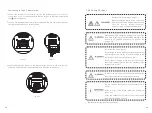
Excessive voltages can destroy the measuring device
Only use measuring devices with a DC input voltage
range up to at least 1,000 Vdc.
1
.
Check the connection cables of the PV modules for correct polarity and make sure
that the maximum input voltage of the inverter is not exceeded.
2
.
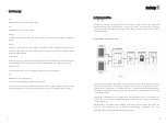
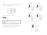
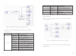
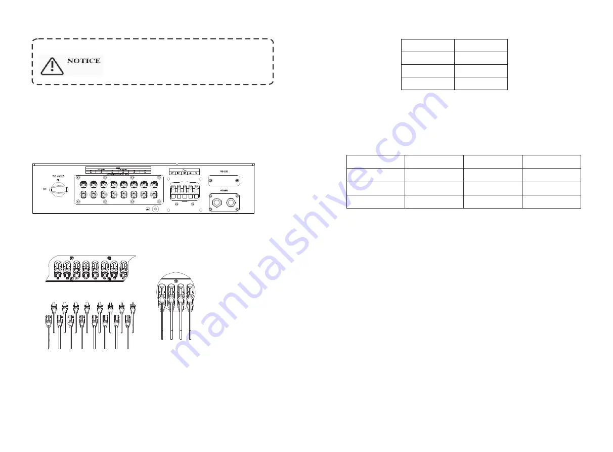
The diagram drawing of DC side is shown as below, notice that the connectors are
in paired (male and female connectors). The connectors for PV arrays and inverters
are H4 (AMPHENOL) connectors;
Fig 5
.
21
Fig 5
.
22
3. Check the assembled DC connectors for correct polarity and connect them to the
inverter.
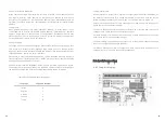
4. The maximum MPP tracker currents are varying from different inverter types.
Type
30000 TL3
33000 TL3
40000 TL3
Max.current
35A
38A
38A
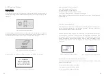
5.In order to seal the inverter, all unneeded DC inputs must be closed with sealing
plugs:
Cable requirements:
30000 TL3
33000 TL3
40000 TL3
Model
2.05
2.05
2.05
Diameter(mm)
3.332
3.332
3.332
Area(mm²)
12
12
12
AWG
5.4.4 Grounding
AC Grounding
The Growatt TL3 must be connected to the AC grounding conductor of the power
distribution grid via the ground terminal (PE).
PV Grounding
The grounding conductor in the framework of the PV array must be connected to the
PV grounding conductor and the DC grounding conductor. The cross-section of the
grounding conductor corresponds to the cross-section of the largest conductor in the
DC system.
DC Grounding Conductor
A DC grounding conductor may be required by the Authority Having Jurisdiction
(AHJ). Use the terminal block for the PV grounding conductor and DC grounding
conductor.


