39
40
Setting Bluetooth of extern wireless
Setting Zigbee of Intern wireless
Setting Wifi of intern wireless
Setting inverter time
Input password->Setting->Extern Wireless->Bluetooth. Knock three times to save
RS232 .Knock four times to exit the setting.
Input password->Setting->intern Wireless->Zigbee->channel->is set the channel of
intern Zigbee. Double knock the enclosure lid ready to input the Channel. Single
knock to change value of first, double knock enter into next position. Knock three
times to save the channel. Knock four times to exit the setting.
Input password->Setting->intern Wireless->Zigbee->channel->PIN->is set the PIN of
intern Zigbee. Double knock the enclosure lid ready to input the PIN. Single knock to
change value of first, double knock enter into next position. Knock three times to
save the PIN. Knock four times to exit the setting.
Input password->Setting->intern Wireless->wifi. Knock three times to save RS232
.Knock four times to exit the setting.
Set Bluetooth of intern wireless
Input password->Setting->intern Wireless->Bluetooth. Knock three times to save
RS232 .Knock four times to exit the setting.
Inverter provides a system clock; user must set the system time after installation, as
the historical statistic data for a period were based on the clock. User can set the
following time parameters: year, month, day, hour, minute.
Input password->Setting-> 2009/03/27 00:38 ->is the current time. Double knock to
go into setting. Single knock to change time. Konck three times to save time. Knock
four times to exit setting. See Fig 6.3.6 for reference
Power: 3385.1W
2009/03/27 00:38
Fig 6.3.9 current time
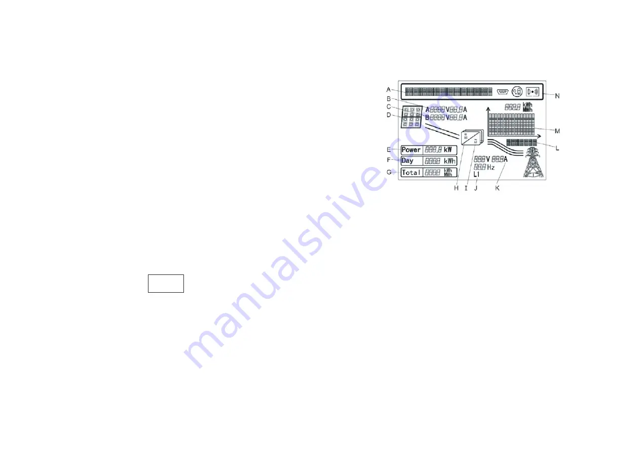
6.4 M3 LCD Display
6.4.1 Graphic display
Position
Detail
A
Text line for displaying an event
B
Input voltage and current of MPPTA
C
Input voltage and current of MPPTB
D
PV array A and B, Light when the array voltage is above
the start voltage(150Vdc)
E
Current power
F
Daily energy
G
Total energy generated since the inverter was installed
H
Light when the array voltage is above the start voltage(150Vdc)
I
Lighted when “H” is lighted and feed-in
Output phase of the line conductor, switch every 5 seconds.
J
Output voltage /current /frequency of the line conductor
K
Graphical display of the inverter energy/power
L
M


