30
29
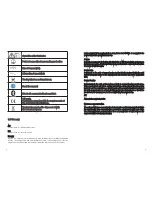
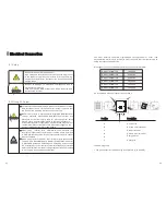
When the cables of AC side and DC side are all well connected, before commissioning, the
country safety standard must be selected by the DIP switch.
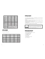
The DIP switch is composed of five-digit binary number PINS. The different combination of the
five PINS can represent different inverter's model, which is corresponding to the local grid
standard. Each small white PIN has two statuses, when set upward to 'ON', its value turns to
'1', when set downward, its value turns to'0'. Concerning the matching of the PIN status and
the country safety standard, please refer to the attached table.
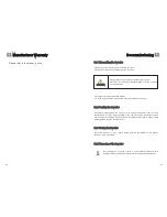
Do not disconnect the DC connectors under load.
Improper operation during the wiring process can cause
fatal injury to operator or unrecoverable damage to the
inverter. Only qualified personnel can perform the wiring
work.
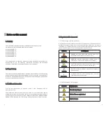
Commissioning
7
7.1 General LCD display
7.1.1 Power on display
Requirements
:
The AC cable is correctly connected.
The DC cable is correctly connected.
The country is set incorrectly(See accessory.)
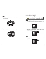
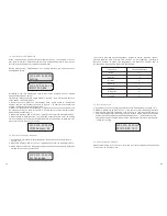
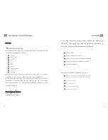
When inverter powered on, LCD background will light automatically. Starting-up
display sequence, once the PV power is sufficient, inverter displays information as
shown in the flow chart as follow:
Module: xxxxxx
SerNo: xxxxxxxxxx
FW Version: x.x.x
Connect in: xxS
Connect : OK
xxxx.xVA xxxx.x W
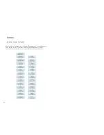
7.1.2 LCD Display when background light off
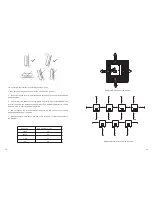
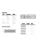
After power on information displayed, there will be another 4 interfaces displayed
in turn, if there is no knock signal input.
DANGER
WARNING
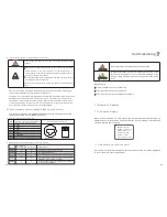
6.7.2 DIP switch option corresponding to the country
When setting the DIP, you must turn off the AC breaker and DC
breaker.
After setting the DIP, please power on the inverter and check the
model display. If the last character of the model name is
corresponding to the country safety standard as the above table, it
means your setting is successful.
You should change the time displayed on the LCD of inverter to your
local time after inverter starts up.
DANGER
!
NOTICE
If the country is set incorrectly, please shut down the inverter and set
again.
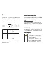
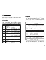
6.8 Inverter demand response modes (DRMs,only for Australia)
This series inverter has the function of demand response modes,moreover, We
use RJ45 socket as inverter DRED connection.
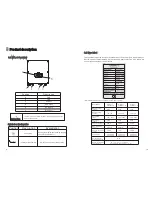
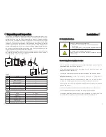
6.8.1 RJ45 socket pin assignment
Assignment for inverterscapable of
both charging and discharging
PIN
1
DRM5
2
DRM6
3
DRM7
4
DRM8
5
RefGen
6
COM/DRM0
7
/
8
/
6.8.2 Method of asserting demand response modes
MODE
Rj45 socket
Asserted by shorting pins
Requirement
DRM0
DRM5
DRM6
DRM7
DRM8
5
6
Operate the disconnection device
Do not generate power
Do not generate at more than 50% of rated power
Do not generate at more than 75% of rated power
AND Sink reactive power if capabie
Increase power generation (subject to constraints
from other active DRMs)
1
5
2
5
3
5
4
5
1
→
8
Pin Assignments Front View
RJ45 Socket
12345678
RJ45 Plug

