background image

35

36

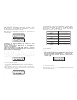
According  to  the  LCD  display,you  need  to  input  three  numbers:  123.You  should 
finish several steps as below:

1.When the LCD stays bright, single knock to ‘Setting…’,and then double knock to  
enter ‘INPUT 123:xxx’interface.

2.  Double  knock  to  make  the  first  number  flash,  single  knock  to  change  the 
number,  and  the  first  number  you  need  to  input  is  ‘1’.  Double  knock  to  enter  the 
second  number while the first number was ‘1’.

3.  When  the  second  number  is  flashing  ,single  knock  to  change  the  number,and 
the second number you need to input is ‘2’. Double knock to enter the last number 
while the first number was ‘2’.

4. When LCD displays ‘INPUT 123:123’, triple knock to enter the setting interface.

5. Single knock to ‘COM Address: xxx’, and then double knock to enter the setting 
status, single knock to change the COM Address. When setting finishes, wait for  
30s or triple knock to save your setting. 

7.2.4 Set inverter display language 

1. If you want to set inverter display language, repeat the steps as described in       

     section 7.2.3.

2. When LCD displays ‘INPUT 123:123’, triple knock to enter the setting interface. 

3. Single knock to select the language you want, when setting finishes, wait for 30s 

    or triple knock to save your setting.

7.2.3 Set inverter’s COM address

When communicating with monitoring software or device, the software or device 
may  regard  inverter’s  COM  address  as  communication  address  (Also  may  use 
inverter’s serial number as communication address).

Before  entering  the    ‘COM  Address:  xxx’  setting  interface,you  need  to  enter  a 
password as below:


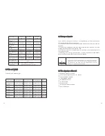
COM Address: 01


Set  Language


The  inverter  provides  seven  languages:  English,  German,  Spanish,  Italian  , 
French,Hungarian  and  Turkish.  The  number  on  Set  language  interface  is 
sequence  number  of  these  five  languages,  the  sequence  number  and  its 
corresponding language are showing in Table below:

Language

Sequence Number

Italian

English

German

Spanish

French

0

1

2

3

4

7.2.5 Set inverter time 

1.


If you want to set inverter time, repeat the steps as described in section 7.2.3.

2.


When LCD displays ‘INPUT 123:123’, triple knock to enter the setting interface.

3.


Single knock until LCD displaying ‘xxxx/xx/xx  xx:xx’, and then double knock to 


enter the setting status, the numbers begin to flash. Single knock to change the 


number, each knock makes the flashing number add ‘1’, and double knock to 


shift to next number setting. When setting finishes, wait for 30s or triple knock


to save your setting.

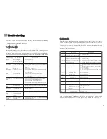
7.2.6 Inverter faulty messages 

When system faulty or inverter error occurred, inverter will display faulty message 
or error code on its LCD screen.


INPUT 123:XXX


Hungarian

5

Turkish

6


2015/09/03  15:11

4505.5VA  4485.5W

4505.5VA  4485.5W

4505.5VA  4485.5W

4505.5VA  4485.5W


4505.5VA  4485.5W

Setting…

Summary of Contents for Growatt 2500MTL-S

Page 1: ...tt 5500MTL S Growatt 3600MTL S S S S Installation Operation Manual Shenzhen Growatt New Energy Technology CO LTD Building B Jiayu Industrial Park 28 GuangHui Road Shiyan Street Baoan District Shenzhen...

Page 2: ...n Unpacking and inspection list 1 2 3 4 2 1 Intended Use 2 2 Qualification of skilled person 2 3 Safety instruction 2 4 Assembly Warnings 2 5 Electrical Connection Warnings 2 6 Operation Warnings 3 1...

Page 3: ...shooting 10 6 1 Safety 6 2 Wiring AC Output 6 3 connecting the second protective conductor 6 4 Connecting the PV Array DCinput 6 5 Using shinetool to set the information of the inverter 6 6 Grounding...

Page 4: ...nual GROWATT NEW ENERGY TECHNOLOGY CO LTD accepts no responsibilities to inform the users 1 4 1 Warnings in this document A warning describes a hazard to equipment or personnel It calls attention to a...

Page 5: ...Power is an instantaneous value It displays the power your inverter is currently feeding into the power distribution grid Power rate is the radio of current power feeding into the power distribution...

Page 6: ...due to the fact that the inverter would otherwise automatically disconnect from the electricity grid as a protective measure 2 2 Qualification of skilled person This grid tied inverter system operate...

Page 7: ...n use the AC current gernerated as follows CAUTION Energy flows into the house grid The consumers connected for example household devices or lighting consume the energy The energy left over is fed int...

Page 8: ...ight hand side of the enclosure IP 65 E DC Switch The DC switch of Growatt MTL S series is optional for different countries Information Growatt 2500MTL S 500V 10A 10A 70V 500V 230V 50HZ 2500VA 10 8A 0...

Page 9: ...The storage temperature should be always between 25 and 60 And the storage relative humidity can achieve to 100 If there are a batch of inverters need to be stored the maximum layers for original cart...

Page 10: ...tial damages to device and operators The installation location must be suitable for the inverter s weight and dimensions for a long period time Select the installation location so that the status disp...

Page 11: ...expose the inverter to direct sunlight as this can cause excessive heating and thus power reduction Observe the Min clearances to walls other inverters or objects as shown in the diagram Be sure that...

Page 12: ...location with some cover or protection There must be sufficient clearance between the individual inverters to ensure 5 3 Mounting the Inverter 5 3 1 Mounting the Inverter with bracket Using the mount...

Page 13: ...ly firmly mounted on the wall after carefully checking WARNING Rise up the inverter a little higher than the bracket Considered the weight of them During the process please maintain the balance of the...

Page 14: ...e single phase circuit breaker or other load disconnection unit for each inverter in order to ensure that the inverter can be safely disconnected under load NOTE The inverter is equipped with integrat...

Page 15: ...h sign L N PE on the socket element and tighten the screws firmly Conductor cross section 5 2 mm 10AWG 6 6 mm 9AWG 6 3 connecting the second protective conductor Growatt 3600MTL S Growatt 4200MTL S Gr...

Page 16: ...strings Same type Same quantity of PV modules connected in series String A String input Input 1 String input String B A B Input 2 Growatt MLT 10 MPPT 1 MPPT 2 If the inverter is not equipped with a D...

Page 17: ...shinetool to set the information of the inverter About the software of shinetool and the usage of it please download from the web www ginverter com Download aspx 6 6 Grounding the inverter The inverte...

Page 18: ...ackground light off After power on information displayed there will be another 4 interfaces displayed in turn if there is no knock signal input DANGER WARNING 6 7 2 DIP switch option corresponding to...

Page 19: ...Auto Test State Update Software REMARK PV voltage low Initial waiting System checking System checking Connect to Grid Inverter watt at working System Fault Protection auto test 7 1 3 The Second line c...

Page 20: ...Operate by knock 7 2 1 Knock type and definition The inverter can support three kinds of knock single knock double knock and thrice knock Each kind of knock has different function Refer to specified d...

Page 21: ...cating with monitoring software or device the software or device may regard inverter s COM address as communication address Also may use inverter s serial number as communication address Before enteri...

Page 22: ...u have to set PIN1 of the switch downward to OFF 2 When Exter wireless is selected you have to set PIN1 of the switch upward to ON 7 2 7 AC Error Record Checking When the LCD stays bright single knock...

Page 23: ...please improve the heat dissipation condition Maybe you need to clean the heat sink 9 1 Checking Heat Dissipation 9 2 Cleaning the Inverter If the inverter is dirty turn off the AC breaker and DC swit...

Page 24: ...isconnect the DC switch immediately Auto Test Failed Auto test didn t passed Contact power company By they decide whether to manually cancel 10 2 Errors E Errors E codes identify a possible equipment...

Page 25: ...unscrew the bracket screws CAUTION 12 2 Packing the Inverter If possible always pack the inverter in its original carton and secure it with tension belts If it is no longer available you can also use...

Page 26: ...input current per string of tracker A tracker B 10A 10A 10A 10A 10A 10A Protection devices DC reverse polarity protection yes yes DC switch ratiing for each MPPT yes yes Output Over current protection...

Page 27: ...ion devices DC reverse polarity protection yes yes DC switch ratiing for each MPPT yes yes Output Over current protection yes yes Output Overvoltage Protection varistor yes yes Ground fault monitoring...

Page 28: ...cm 49 50 Shipped to a Growatt service centre for repair or repaired on site or exchanged for a replacement device of equivalent value according to model and age The warranty shall not cover transport...

Page 29: ...sonal access code if you need it please contact with GROWATT 15 2 Download Address www ginverter com Contact 16 If you have technical problems about our products contact the GROWATT Serviceline We nee...

Page 30: ...y Knock to make the display bright knock to Enable Auto test double knock to enter Waiting to start the inverter will start auto test and wait for the test result When the inverter start auto test the...

Reviews: