编号:
GR-UM-C -00
24
/
57
WARNING
not carry out warranty and assumes any responsibility.
7.
Debugging
7.1
Debug Inverter
1
)
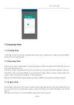
Close the DC switch on the inverter. As long as the input DC voltage is greater than 250V, the inverter display will
display the following message: If there is no mains connection error, the inverter LED will turn red. If other information is
displayed, please refer to Chapter 9. If the debugging process encounters an unsolvable problem, please contact customer
service and perform the next step.
2
)
Close the circuit breaker or switch between the inverter and the grid. The inverter starts the self-test countdown. After the
self-test is normal, it will be connected to the grid.
3
)
In normal operation, the leaves of the inverter indication window will turn green.
4) Complete debugging.
If the inverter is stored over one month, its default time and date may looks wrong, the time
and date should be reset before connection to the grid.
7.1.1 Set the PV inverter Communication Address
After the inverter is turned on normally, the inverter communication address can be set through RS485, USB to WIFI
module or server webpage. When the inverter is connected by RS485 and multi-machine parallel communication, the
inverter should be set to different communication address; when the single machine communicates, the factory default
communication address can be used directly. Note: The inverter communication address can be set from 1 to 254.
7.1.1.1 ShineBus Sets the Communication Address
The communication address of the inverter can be modified by the PC software ShineBus, which is performed by a
professional.
7.1.1.2 Mobile APP Set Communication Address
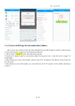
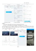
Refer to Section 8.2 Local Data Monitoring, download the mobile app and log in to the monitoring interface to modify the
communication address. This operation is performed by a professional.
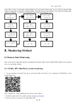
1> Select "Parameter Settings".
2> Enter the control password. (First time you need to set the control password, click "Reset Password", jump to the page,
enter the OSS account and password, the distributor and installer can apply for the OSS account to Growatt, click "Login",
set Control password, the relevant settings can be used after the setting is successful.)
3> Select the setting item "Communication Address".
4> Click "Read" in the upper right corner to get the original communication address of the machine.
5> Set the inverter communication address.
6> Read the inverter communication address and confirm that the setting is successful.

