background image

14

13

5.2 Selecting the installation location

Ø

Ø

Ø
Ø

Ø

Ø

Ø
Ø
Ø

This  is  guidance  for  installer  to  choose  a  suitable  installation  location,  to  avoid   

potential damages to device and operators. 

The installation location must be suitable for the inverter's weight and dimensions 

for a long period time.

Select the installation location so that the status display can be easily viewed.
Do not install the inverter on structures constructed of inflammable or thermolabile 

materials.
Never  install  the  inverter  in  environment  of  little  or  no  air  flow,  nor  dust 

environment. That may derate the efficiency of the cooling fan of the inverter.

The  Ingress  Protection  rate  is  IP65  which  means  the  inverter  can  be  installed 
outdoors and indoors.
The humidity of the installation location should be 0~100% without condensation.
The installation location must be freely and safely to get at all times.
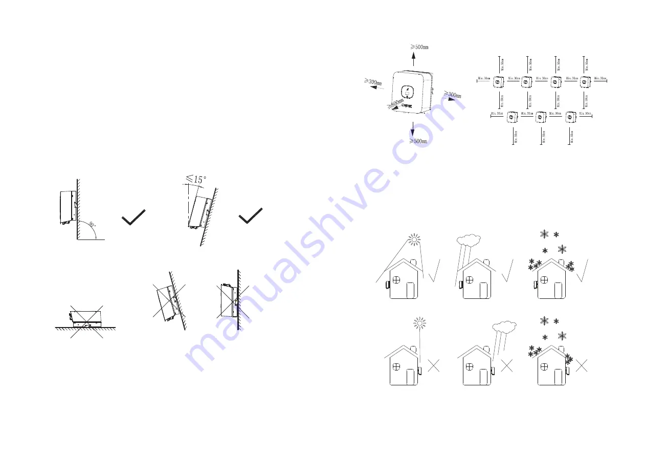
Vertically installation and make sure the connection of inverter must be downwards. 

Never install horizontal and avoids forward and sideways tilt.

Ø
Ø
Ø

Ø

Ø

Ø

Be sure that the inverter is out of the children's reach.
Don't put any things on the inverter. Do not cover the inverter.
Do not install the inverter near television antenna or any other antennas and 

antenna cables.

Inverter requires adequate cooling space. Providing better ventilation for the 

inverter to ensure the heat escape adequately. The ambient temperature should be 

below 40°C to ensure optimum operation. 

Do not expose the inverter to direct sunlight, as this can cause excessive heating and 

thus power reduction.

Observe the Min. clearances to walls, other inverters, or objects as shown below:

Ambient dimensions of one inverter

Ambient dimensions of series inverters

Ø

Ø

There  must  be  sufficient  clearance  between  the  individual  inverters  to  ensure  that 

the cooling air of the adjacent inverter is not taken in.

If necessary, increase the clearance spaces and make sure there is enough fresh air 

supply to ensure sufficient cooling of the inverters.

The  inverter  can't  install  to  solarization

drench

firn  location.  We  suggest  that  the 

inverters should be installed at the location with some cover or protection

.

Summary of Contents for MIC 1000TL-X

Page 1: ...Manual Growatt New Energy Shenzhen Growatt New Energy Co Ltd 4 13 F Building A Sino German Europe Industrial Park Hangcheng Ave Bao an District Shenzhen China 86 0755 2747 1942 www ginverter com T E...

Page 2: ...on of skilled person 2 3 Safety instruction 2 4 Assembly Warnings 2 5 Electrical Connection Warnings 2 6 Operation Warnings 1 1 Validity 1 2 Target Group 1 3 Additional information 1 4 Symbols in this...

Page 3: ...ion 14 2 DC AC connector info 14 3 Torque 14 4 Accessories 6 Electrical connection 13 Decommissioning 7 Commissioning 14 Technical Data 7 1 Start the inverter 7 2 General setting 7 3 Advanced setting...

Page 4: ...equipment or personal injury This manual describes the assembly installation commissioning and maintenance of the following Growatt Inverter model MIC 600TL X MIC 750TL X MIC 1000TL X MIC 1500TL X MI...

Page 5: ...built according to all required safety rules Nevertheless improper use may cause lethal hazards for the operator or third parties or may result indamage to the units and other property Principle of a...

Page 6: ...20 minutes discharge The components in the inverter are live Touching live components can result in serious injury or death DANGER WARNING Ensure all connectors are sealed and secure during operation...

Page 7: ...uch symbol Touch button We can switch the OLED display and set parameter by touching Inverter status symbol Indicates inverter operation status Red Fault Green Nomal Red leaf flash Warning or DSP Prog...

Page 8: ...4 3A 14 3A 3 6A 4 8A 7 1A 0 8leading 0 8lagging 0 8leading 0 8lagging IP 65 IP 65 with derating above 45 C 113 F 25 60 13 140 F with derating above 45 C 113 F 25 60 13 140 F 282mm 11 1inch 274mm 10 78...

Page 9: ...Growatt assumes no responsibility for compliance to EMC regulations for the complete system All electrical installations shall be done in accordance with the local and national electrical codes Do no...

Page 10: ...horizontal and avoids forward and sideways tilt Be sure that the inverter is out of the children s reach Don t put any things on the inverter Do not cover the inverter Do not install the inverter nea...

Page 11: ...wall Instead leave 2 to 4mm exposed Falling equipment can cause serious or even fatal injury never mount the inverter on the bracket unless you are sure that the mounting frame is really firmly mount...

Page 12: ...X MIC 600TL X 5A 230V 5A 230V 10A 230V 10A 230V 16A 230V 16A 230V 16A 230V 16A 230V MIC 2000TL X MIC 1000TL X MIC 2500TL X MIC 1500TL X MIC 3000TL X MIC 3300TL X The AC wiring step 1 Uninstall the pa...

Page 13: ...ut or unscrew the threaded sleeve then pull it out Wire suggestion length Conductor cross section Conductor cross section Max cable length Max cable length MIC 600TL X MIC 3300TL X MIC 2000TL X MIC 10...

Page 14: ...n circuit voltage Voc of each PV string is less than the maximum input voltage of the inverter Check the design of the PV plant The Max open circuit voltage which can occur at solar panels temperature...

Page 15: ...en up the cap on the terminal Step 3 the inverter Push the threaded sleeve to connection terminal until both are locked tightly on Uninstall signal connector 6 5 Connecting signal cable This series in...

Page 16: ...u can connect smart meter or CT but CT is optional The smart meter model is Eastron SDM230 Modbus The CT Model is TOP 90 S10 SP4 LEM The primary aperture is 10mm output cable length is 5m The arrow on...

Page 17: ...electric arcs AFCI on the PV side 6 9 2 Danger information Danger of fire from electric arc Only test the AFCI for false tripping in the order described below Do not deactivate the AFCI permanently I...

Page 18: ...or confinmation Previous menu Confirm country setting or Number recover default value Information Country setting When the inverter start up we need to select the right country if we don t select any...

Page 19: ...age Double touch to confirm you setting Set the language as described below Set Language English General Advanced Set parameter Set Language English General Set Comaddr Advanced 001 Set parameter The...

Page 20: ...ced Password 123 This series inverter provides two RS485 ports You can monitor one or more inverters by RS485 Another RS485 port is for smart meter Export limitation functionality Information Perform...

Page 21: ...an the enclosure lid the display and the LEDs using only a wet cloth Do not use any cleaning agents e g solvents or abrasives Check for externally visible damage and discoloration of the DC Disconnect...

Page 22: ...the invert 2 If error message still exists contact Growatt PV Isolation Low Error 203 AC V Outrange Error 300 No AC connection Error 302 PE abnormal Error 303 Insulation problem Utility grid voltage...

Page 23: ...sage still exists contact manufacturer 1 Check if the meter is on 2 Check the inverter and the meter connection is normal 11 4 Inverter fault Error code Meanings Suggestion Error 402 Error 404 Error 4...

Page 24: ...sories together with household waste Please accordance with the disposal regulations for electronic waste which apply at the installation site at that time Ensure that the old unit and where applicabl...

Page 25: ...n Interfaces 274 254 138 6 0 kg 25 C 60 C 25 dB A 4000m 0 5W transformerless Natural convection IP65 0 100 VP D4 MC4 Optional AC connector Display RS485 USB WIFI GPRS 4G LAN RF Warranty 5 10 years OLE...

Page 26: ...III General data Dimensions W H D in mm Weight Operating temperature range 274 254 138 6 2kg 6 0kg 25 C 60 C Noise emission typical Altitude Internal consumption at night Topology Cooling Protection d...

Page 27: ...with USB interface 4G monitor with USB interface RF monitor with USB interface LAN monitor with USB interface 15 Compliance Certificates Certificates With the appropriate settings the unit will comply...

Reviews: